16 | Unit installation
Installer and user reference guide
53
FXFA20~125A2VEB
VRV system air conditioner
4P599624-1A – 2020.06
NOTICE
The equipment described in this manual may cause electronic noise generated from
radio-frequency energy. The equipment complies to specifications that are designed
to provide reasonable protection against such interference. However, there is no
guarantee that interference will not occur in a particular installation.
It is therefore recommended to install the equipment and electric wires in such a
way that they keep a proper distance from stereo equipment, personal computers,
etc.
In places with weak reception, keep distances of 3 m or more to avoid
electromagnetic disturbance of other equipment and use conduit tubes for power
and transmission lines.
▪ Take care that in the event of a water leak, water cannot cause any damage to
the installation space and surroundings.
▪ Choose a location where the operation noise or the hot/cold air discharged from
the unit will not disturb anyone.
▪ Air flow. Make sure nothing blocks the air flow.
▪ Drainage. Make sure condensation water can be evacuated properly.
▪ Paper pattern for installation (upper part of packing) (accessory). When
selecting the installation location, use the paper pattern. It contains the
dimensions of the unit and the required ceiling opening.
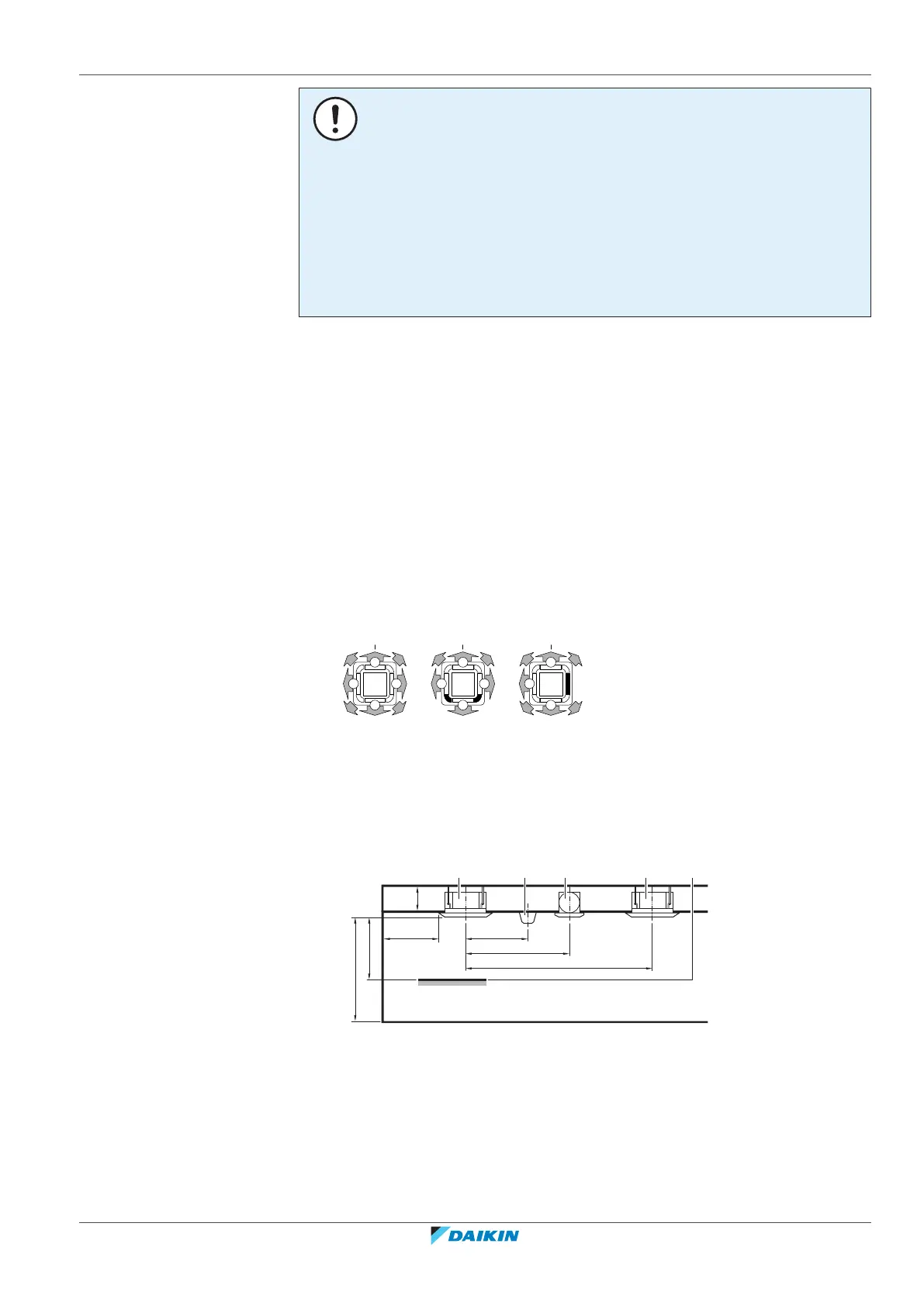
▪ Air flow directions. You can select different air flow directions. Choose the one
best suited for the room. For more information, see the installation manual of
the optional blocking pad kit.
Example:
a All-round air flow
b 4-way air flow (with closed corners) (optional blocking pad kit required)
c 3-way air flow (optional blocking pad kit required)
▪ Ceiling insulation. When conditions in the ceiling exceed 30°C and a relative
humidity of 80%, or when fresh air is inducted into the ceiling, then additional
insulation is required (minimum 10mm thickness, polyethylene foam).
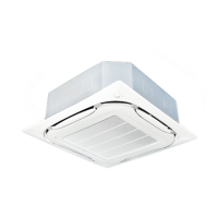
▪ Spacing. Mind the following requirements:
(mm)
≥1500
≥
2000
≥
4000
≥1500
A
B
C
ba dac
A Minimum distance to the wall (see below)
B Minimum and maximum distance to the floor (see below)
C 20~63 class:
≥224 mm: In case of installation with standard decoration panel
≥266 mm: In case of installation with design decoration panel
≥304 mm: In case of installation with self-cleaning decoration panel
≥274 mm: In case of installation with fresh air intake kit
80~100 class:
≥266mm: In case of installation with standard decoration panel
≥308mm: In case of installation with design decoration panel
≥346mm: In case of installation with self-cleaning decoration panel
≥316mm: In case of installation with fresh air intake kit
125 class:
≥308 mm: In case of installation with standard decoration panel