16 | Unit installation
Installer and user reference guide
54
FXFA20~125A2VEB
VRV system air conditioner
4P599624-1A – 2020.06
≥350 mm: In case of installation with design decoration panel
≥388 mm: In case of installation with self-cleaning decoration panel
≥358 mm: In case of installation with fresh air intake kit
a Indoor unit
b Lighting (the figure shows ceiling-mounted lighting, but recessed lighting is also allowed)
c Air fan
d Static volume (example: table)
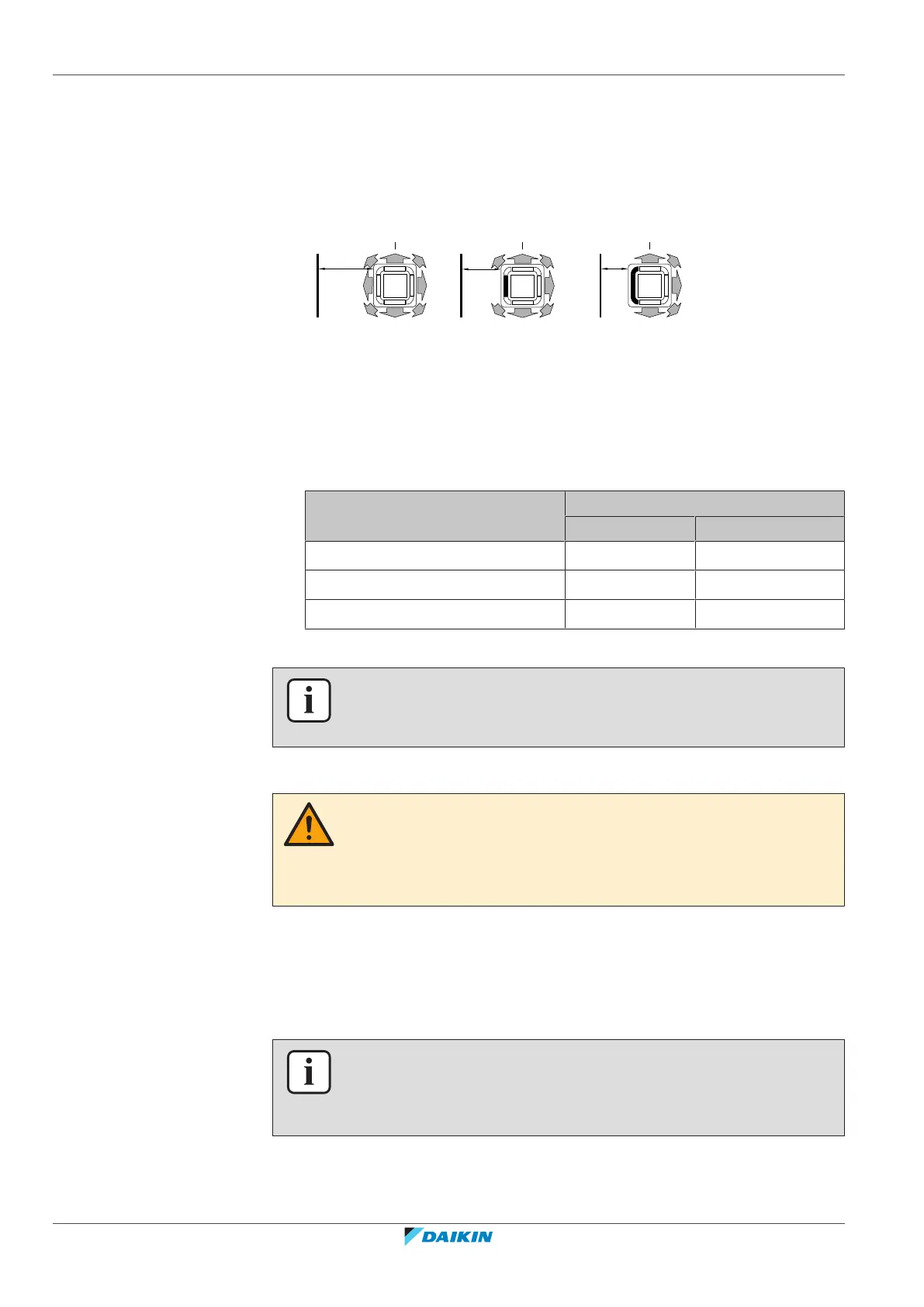
▪ A: Minimum distance to the wall. Depends on the air flow directions towards
the wall.
a Air outlet and corners open
b Air outlet closed, corners open (optional blocking pad kit required)
c Air outlet and corners closed (optional blocking pad kit required)
▪ B: Minimum and maximum distance to the floor:
- Minimum: 2.7m to avoid accidental touching.
- Maximum: Depends on the air flow directions and the capacity class. Also make
sure the "Ceiling height" field setting corresponds with the actual situation. See
"20.1Field setting"[474].
If air flow direction… Then B
FXFA20~100 FXFA125
All-round ≤3.5m ≤4.2m
4-way
(a)
≤4.0m ≤4.5m
3-way
(a)
≤3.5m ≤4.2m
(a)
Optional blocking kit required
INFORMATION
Some options may require additional service space. Refer to the installation manual
of the used option before installation.
Minimum floor area requirements
CAUTION
The total refrigerant charge in the system cannot exceed the requirements for
minimum floor area of the smallest room that is served. For minimum floor area
requirements for indoor units, see the installation and operation manual of the
outdoor unit.
16.2 Mounting the indoor unit
16.2.1 Guidelines when installing the indoor unit
INFORMATION
Optional equipment. When installing optional equipment, also read the installation
manual of the optional equipment. Depending on the field conditions, it might be
easier to install the optional equipment first.
▪ Decoration panel. Install the decoration panel always after installing the unit.