18 | Electrical installation
Installer and user reference guide
71
FXFA20~125A2VEB
VRV system air conditioner
4P599624-1A – 2020.06
d Tie wrap
e Connection of user interface and transmission cable
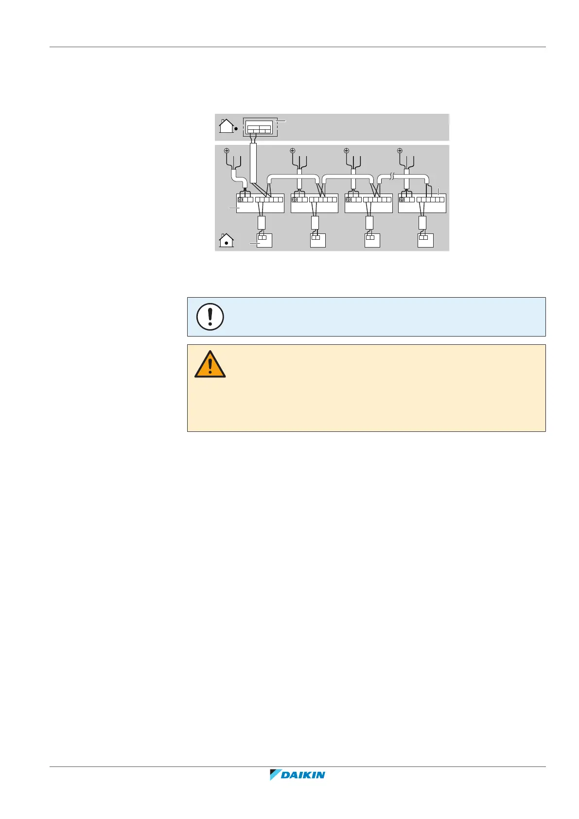
Complete system example
1 user interface controls 1 indoor unit.
LN LN LN
IN/D OUT/D
F
1 F2 F1 F2
Control box
P
1
P
2
P
1
P
2
P
1
P
2
P
1
P
2
P
1
P
2
F
1
F
2
T
1
T
2
P
1
P
2
F
1
F
2
T
1
T
2
P
1
P
2
F
1
F
2
T
1
T
2
P
1
P
2
F
1
F
2
T
1
T
2
N L
a
d
c
b
LN
N L N L N L
a Outdoor unit
b Indoor unit
c User interface
d Most downstream indoor unit
NOTICE
Group control connection is NOT allowed.
CAUTION
▪ Each indoor unit has to be connected to a separate user interface. Only a safety
system compatible remote controller can be used as the user interface. See
technical data sheet for remote controller compatibility (e.g. BRC1H52/82*).
▪ The user interface has to be put in the same room as the indoor unit. For details,
please refer to the installation and operation manual of the user interface.