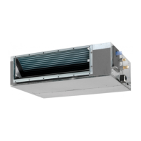
4
• Where the ceiling’s lower surface is not remarkably
inclined.
• Where there is
strength to withstand the mass
of the indoor unit. (If the strength is
the in-
door unit may vibrate and get in contact with the ceiling
and generate unpleasant chattering noise.)
• Where a space
for installation and service can
be ensured. (Refer to Fig. 1 and Fig. 2)
• Where the piping length between the indoor and the out
-
door units is ensured within the allowable length. (Refer
to the installation manual attached to the outdoor unit.)
• Where there is no risk of
gas leak.
[ Required installation space ]
Figures indicate the minimum required installation space.
Maintenance
space for
drain pan
Maintenance
space for
electrical
components
Secure the maintenance
space for the drain pan and
electrical components.
450mm
or more
Fig. 1
Floor
Ceiling
2500mm
or more
H2 or more*
20mm
or moreH1=245mm*
Fig. 2
• * Dimension H1 indicates the product height.
• * Secure a downward slope of at least 1/100
in
7. DRAIN PIPING WORK and determine dimension H2.
<Failure example>
If there is an obstacle in the airflow path or proper installation
space is not provided, the indoor unit will cause air volume
reduction and take in air blown out of the indoor unit,
thus resulting in performance degradation or turning the
thermostat OFF frequently.
CAUTION
• Install the indoor and outdoor units, power supply wiring,
remote controller wiring and transmission wiring at least
1 meter away from televisions or radios to prevent image
interference or noise.
(Depending on the radio waves, a distance of 1 meter may
not be
to eliminate the noise.)
• Install the indoor unit as far as possible from
lamps.
If a wireless remote controller kit is installed, the transmis-
sion distance may be shorter in a room where an electronic
lighting type (inverter or rapid start type)
lamp is
installed.
If you set the fan speed at thermostat OFF, did you
explain the set fan speed to the cus tomer.
Have you handed the operation manual and the
installation manual to the customer?
Have you checked that there is no generation
of abnormal noise (i.e., noise resulting from
contamination or missing parts)?
Is the printed circuit board switch not on the
emergency (EMG.) side?
The switch is factory set to the normal (NORM.) side.
If an optional accessory is in use, did you check the
operation of the optional accessory and make field
settings as needed?
Is the remote controller icon displayed? Is the
remote controller connected to the master unit if the
system is in simultaneous multi operation?
Have you explained failure examples of
3. SELECTION OF INSTALLATION LOCATION?
Points of the operation explanation
In addition to the general usage, since the items in the
operation manual with the
WARNING and
CAUTION marks are likely to result in human bodily
injuries and property damages, it is neces sary not only
to explain these items to the customer but also to have
the customer read them.
Furthermore, it is necessary to have the customer read
through the troubleshooting items while explaining the
above items.
3. SELECTION OF INSTALLATION LOCATION
Hold the hangers at 4 locations to move the indoor unit
when unpacking or after unpacked, and do not apply force
to the piping (refrigerant and drain) and air outlet flange.
If the temperature and humidity in the ceiling is likely to
exceed 30°C, RH80%, use the additional insulation stick to
the indoor unit.
Use the insulation such as glass wool or polyethylene
that has thickness of 10 mm or more. However, keep the
insulated outside dimension smaller than the ceiling
opening so that the unit may go through the opening at
installation.
(1) Select
the installation location that meets the following
conditions and get approval of the cus tomer.
• Where the cool and warm air spreads evenly in the
room.
• Where there are no obstacles in the air passage.
• Where drainage can be ensured.

 Loading...


