Installation manual
13
LREQ5~20B7Y1
Air cooled refrigeration condensing unit
4PW74302-1 – 2012.06
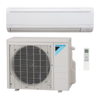
Remote switch wiring connections
• When installing a remote switch, clamp as indicated by the
following diagram:
X3M wire specifications
Wiring connection for low-noise mode
• Wiring connection for low-noise mode: clamp as indicated by the
following diagram:
X1M (A5P) wire specifications
• For Remote switch, use non-voltage contact for microcurrent (not
more than 1 mA, 12 V DC)
• If the remote switch will be used to start and stop the unit, set the
operating switch to “REMOTE”.
Precautions for terminal connections
• Be sure to use ring-type crimp-style terminals provided with
insulation sleeves.
• Use specified electric wires for the wiring and secure the wiring so
that external force will not be imposed on the terminal block.
• Use an appropriate screwdriver to tighten the terminal screws.
Small-sized screwdriver will damage the screw heads and cannot
tighten the screws properly.
• Do not tighten the terminal screws in excess, otherwise the screws
may be damaged.
• Refer to the following table for the tightening torque values of the
terminal screws.
• Take out the earth wire from the notch of the cup washer and lay
the wire carefully so that other wires will not be caught by the
washer. Otherwise, the earth wire may not contact sufficiently and
the earthing effect of the wire may be lost.
• Do not finish strand wire with solder.
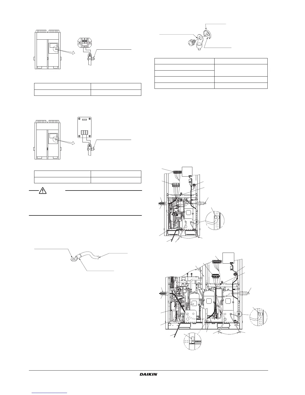
7-4 Procedure for wiring inside units
• Referring to the following figure, secure and wire the power and
transmission wiring using the accessory clamp (1), (2).
• Lay the ground wire so that it will not come in contact with the lead
wires of the compressor. Other equipment will be adversely
affected if the ground wire comes in contact with the lead wires of
the compressor.
• Make sure all wiring do not contact to the pipes (hatching parts in
the figure).
• The transmission wiring must be at least 50 mm away from the
power wiring.
• After wiring work is completed, check to make sure there are no
loose connections among the electrical parts in the control box.
Electric wire thickness
0.75~1.25 mm
2
Max. wiring length 130 m
Electric wire thickness
0.75~1.25 mm
2
Max. wiring length 130 m
 Loading...