• Fully open the shutoff valves on the liquid and gas sides after the
refrigerant replenishment is finished.
The compressor will malfunction if the system is operated with the
shutoff valves closed.
• Apply a screw lock agent to the screws of the valve cover
mounting parts and service ports.
(Otherwise, dew condensation water will intrude and freeze inside
and cause cap deformation or damage, which may result in
refrigerant gas leakage or compressor malfunctions.)
11. TEST RUN
For test run operators
Do not operate the outdoor unit alone on a trial basis.
Test run procedure
Use the following procedure to perform a test run after installation
work is complete for the entire system:
1. Fully open the shutoff valves on the gas and liquid sides of the
outdoor unit.
2. Set the operation switch of the outdoor unit to ON.
Note: Before turning power on, check that the piping cover and
control box lid of the outdoor unit are closed.
3. Check the sealing condition of the outdoor unit through the sight
glass. Make sure that the amount of refrigerant is sufficient.
4. Make sure that cold air blows from the indoor unit.
Check that the internal temperature is dropping.
(Check that the temperature will drop and reach the set
temperature in the internal unit. It will take approximately
40 minutes for the interior temperature of the internal unit to reach
–20°C.)
Check that the indoor unit (for refrigeration or freezing) goes into
defrosting operation.
5.
Turn power off with the operation switch of the outdoor unit set to OFF.
(Stopping unit operation by disconnecting the power supply directly
is dangerous. When the unit is stopped in this manner, its power
outage compensation function may cause it to resume operation as
soon as the power supply is reactivated. Additionally, stopping the
unit in this manner may cause the compressor to fail).
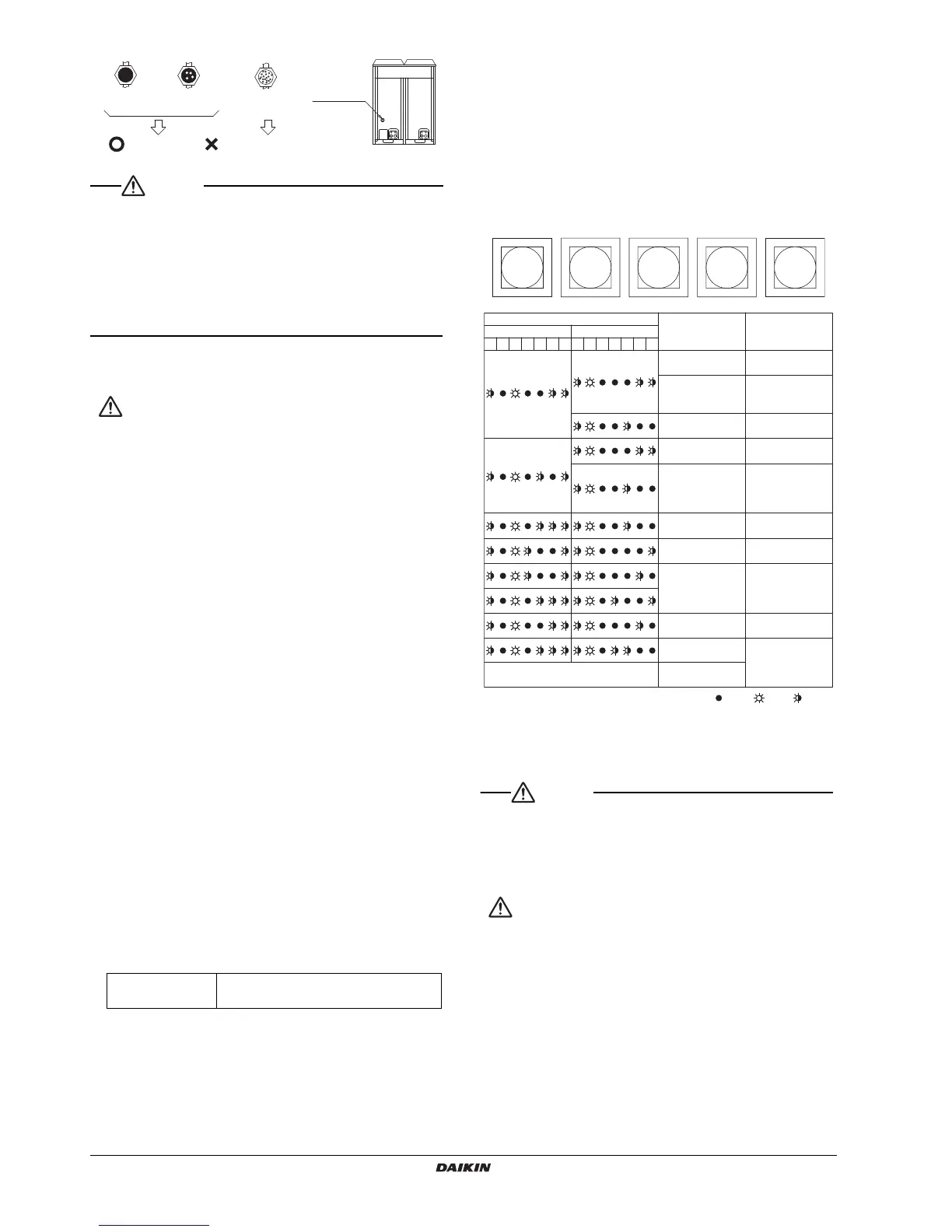
Error diagnosis
• If the system cannot operate normal at the time of test run (i.e., the
H2P indicator is lit), check with malfunction code on the system
with the pushbutton switches on the PCB of the outdoor unit, and
take the following steps.
• Make checks on other malfunction codes and pushbutton switches
by referring to the provided Technical Guide.
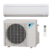
Display
The contents of a LED (H2P) display are as follows.
How to check malfunction code
By operating the pushbutton switches on the PCB, malfunction
code items can be displayed on the condensing unit.
1. Make sure that the LED “H1P” is off.
(If the LED is on, press the MODE button (BS1) once.)
2. Press the MODE button (BS1) once. The LED (H1P) starts
blinking.
3. Press the RETURN button (BS3) to display the first digit of the
malfunction code on the LED.
4. Press the SET button (BS2) to display the second digit of the
malfunction code on the LED.
5. Press the MODE button (BS1) to restore the LED to the original
state.
*1
Set the operation switch to the OFF position to reset the power supply
and then return the operation switch to the ON position to restart the
unit. If the problem persists, refer to the Service Manual.
• Do not disconnect the power supply for 1 minute after setting the
operation switch to ON.
Electric leak detection is performed for several seconds after the
operation switch is set to ON and each compressor starts
operating, so disconnecting the power supply during that time will
result in a false detection.
For dealers
• After the test run is finished, check that the piping cover and front
panel are mounted.
• At the time of delivery to the customer, use the operation manual
and fully explain the handling of the equipment.
• For precautions at the time of delivery, refer to the provided
installation manual for each unit as well.
LED (H2P) display
OFF.....Normal ON.....error
Blinking.....to be prepared
 Loading...