www.DaikinApplied.com 13 IM 1285-4 • MICROTECH III
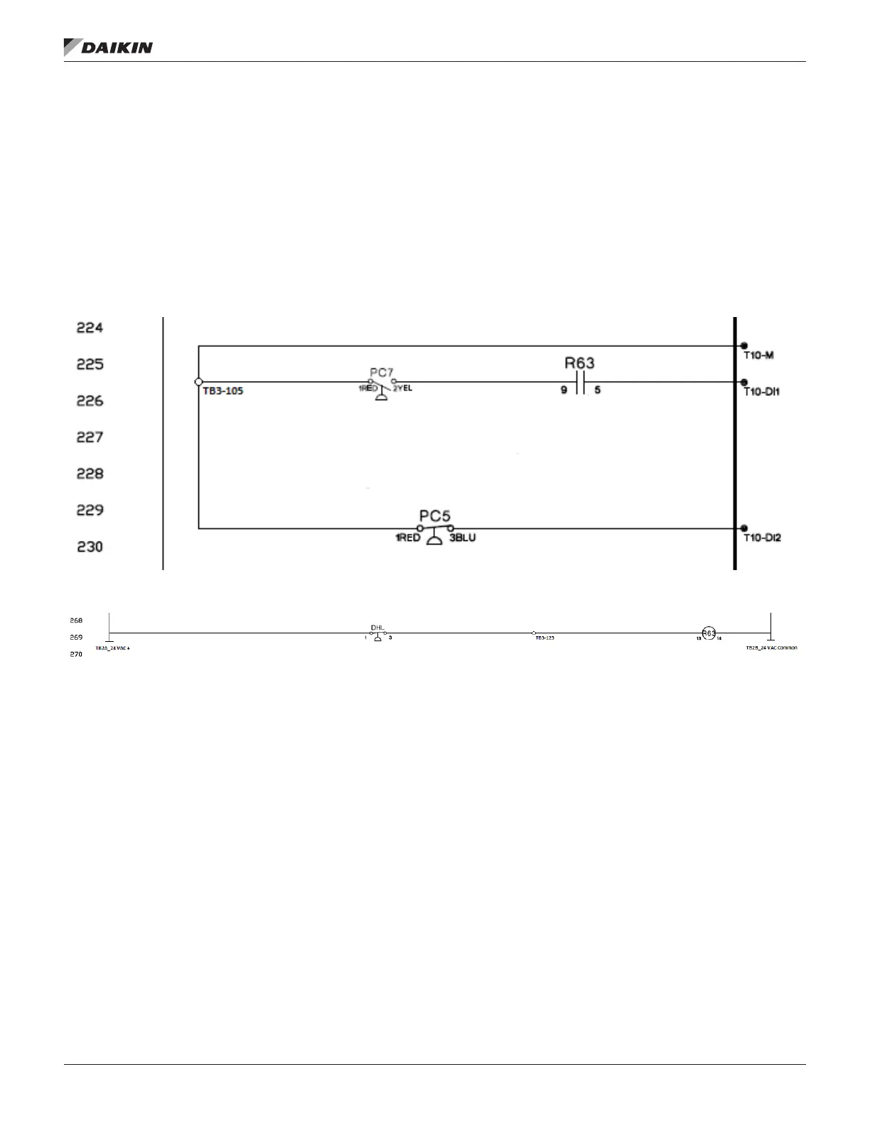
The PC5 pressure switch wires directly to the MT III as shown
below in Figure 17. PC5 is a normally closed switch that
completes a circuit between DI2 and M. If the switch opens, the
circuit breaks and generates a dirty lter alarm.
The PC7 pressure switch is wired in series with the R63 NO
contact and MT III shown in Figure 17. PC7 is a normally
closed switch that completes a circuit between DI1 and M. If
the switch opens, the circuit breaks and an Airow Fault alarm
will occur after three attempts.
The DHL switch is wired in series with the R63 relay shown in
Figure 18. The R63 relay is energized with 24 VAC from TB2A-
104 as long as the DHL switch is closed. Three sets of NO dry
contacts from the R63 relay are wired to the MT III: DI4 (line
220), DI1 (line 225) and DI2 (line 868) on the VFD.
If the unit was selected for constant volume, then no
DHL would be installed.
Figure 17: PC7 Pressure Switch
Figure 18: R63 Relay
 Loading...


