IM 1285-4 • MICROTECH III 34 www.DaikinApplied.com
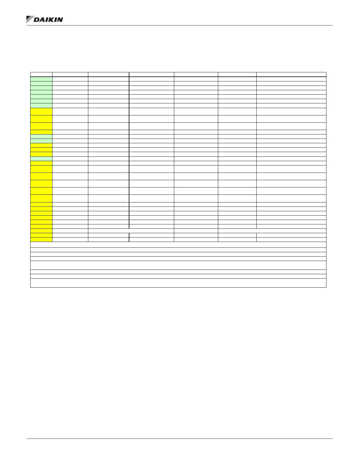
Figure 29: Parameters
On the PC exactly… Appears as…
Regional Settings North America start at 0-0* Basic Settings 0-03 Regional Settings [1] North America Required change to allow many 60 Hz settings
Motor Power [HP] enter dataplate value start at 1-** Load and Motor 1-21 Motor Power [HP] enter dataplate value
Motor Voltage enter dataplate value start at 1-** Load and Motor 1-22 Motor Voltage enter dataplate value
Motor Frequency 60Hz start at 1-** Load and Motor 1-23 Motor Frequency 60Hz Almost always 60 Hz
Motor Nominal Speed 1760 start at 1-** Load and Motor 1-25 Motor Nominal Speed 1760 1760 is close, motor nameplate may be different.
Flying Start Enabled start at 1-** Load and Motor 1-73 Flying Start [1] Enabled
Minimum Reference 00.00 start at 3-0* Reference Limits 3-02 Minimum Reference 00.000 Modbus comms controls the lowest motor speed.
Reference Function Sum start at 3-0* Reference Limits 3-04 Reference Function [0] Sum
Sum of all presets-Writes via modbus to parameter 3-
10. Others will be zero.
Reference 1 Source No Function start at 3-1* References 3-15 Reference 1 Source [0] No function
Duct Static P1: Signal between 53 & 55. Set switch
A53 to ON for ma.
Reference 2 Source No Function start at 3-1* References 3-16 Reference 2 Source [0] No Function
Duct Static P2: Signal between 54 & 55. Set switch
A54 to ON for ma.
Reference 3 Source No Function start at 3-1* References 3-17 Reference 3 Source [0] No Function
Ramp 1 Ramp Up Time 60.00 start at 3-4* Ramp 1 3-41 Ramp 1 Ramp Up Time 60.00s
Ramp 1 Ramp Down Time 60.00 start at 3-4* Ramp 1 3-42 Ramp 1 Ramp Down Time 60.00s
Terminal 27 Mode Input start at 5-00 Digital I/O mode 5-01 Terminal 27 mode [0] Input
Contacts between 27 and 12.
Terminal 29 Mode Output start at 5-00 Digital I/O mode 5-02 Terminal 27 mode [1] Output
If not [1] then 5-31 is locked-out.
Terminal 27 Digital Input External Interlock start at 5-1* Digital Inputs 5-12 Terminal 27 Digital Input [7] External Interlock
Terminal 32 Digital Input Fire Mode start at 5-1* Digital Inputs 5-14- Terminal 32 Digital Input [37] Fire Mode
Terminal 33 Digital input No Operation start 5-1* Digital Inputs 5-15 Terminal 33 Digital Input [0] No Operation
Terminal 29 Digital Output No Operation start 5-3* Digital Outputs 5-31 Terminal 29 Digital Output [60] Comparator 0
Must set 5-02 first, then 13-10, 13-11, and 13-12, then
5-31 last.
Protocol FC (required for write to drive) start at 8-3* FC Port Settings 8-30 Protocol [2] RTU Modbus
Change via keypad, power cycle required. Wired
+@#68, -@ #69, Shield at #61
Address 1 (found at default) start at 8-3* FC Port Settings 8-31 Address [1]SAF,[2]RAF,[3]EXH
Change via keypad, power cycle required. Choose
MT3 address of VFD to be controlled
Baud rate 9600 Baud (found at default) start at 8-3* FC Port Settings 8-32 Baud rate [3] 19200 Baud
Change via keypad, power cycle required. 19,200
required for MT3 coms
Parity / Stop Bits Even Parity,1 Stop Bit (at default) start at 8-3* FC Port Settings 8-33 Parity, Stop Bits [3] No Parity, 2 Stop Bits
Change via keypad, power cycle required. Required
for MT3 comms
Minimum Response Delay need to enter new value = 100 start at 8-3* FC Port Settings 8-35 Minimum Response Delay 100ms
MT3 best operation this setting
Protocol Logic OR (default) 8-50* Digital Bus 8-50 Coasting Select [3] Logic OR
MT3 best operation this setting
Start Select Logic OR (default) 8-50* Digital Bus 8-53 Start Select Logic OR [3] Logic OR
Modbus OR Input 53
Comparator Operand Alarm Number Comparators-1 13-1* 13-10 Comparator Operand [20] Alarm Number
Set 5-02 first, then 13-10, then 13-11 next
Comparator Operator (equal) Comparators-1 13-1* 13-11 Comparator Operator [1] = (equal)
Set 13-10 first, then 13-11, then 13-12 next
Comparator Value 60.000 Comparators-1 13-1* 13-12 Comparator Value 60.000
Set 13-11 first, then 13-12, then 5-31 last
Set to IN at highest address of 8-31 Set to IN at highest address of 8-31
set to = I set to = I
Switch is behind keypad.
set to = I set to = I
Switch is behind keypad.
P:\Engineering\ENG_data\AFD PARAMETER SOURCE FILES\170632800.xls
MT3 FC102 All Modbus
 Loading...


