IM 893-10 • ROOFPAK SINGLEZONE UNITS 4 www.DaikinApplied.com
InTroduCTIon
Unit Description
Typical Component Locations
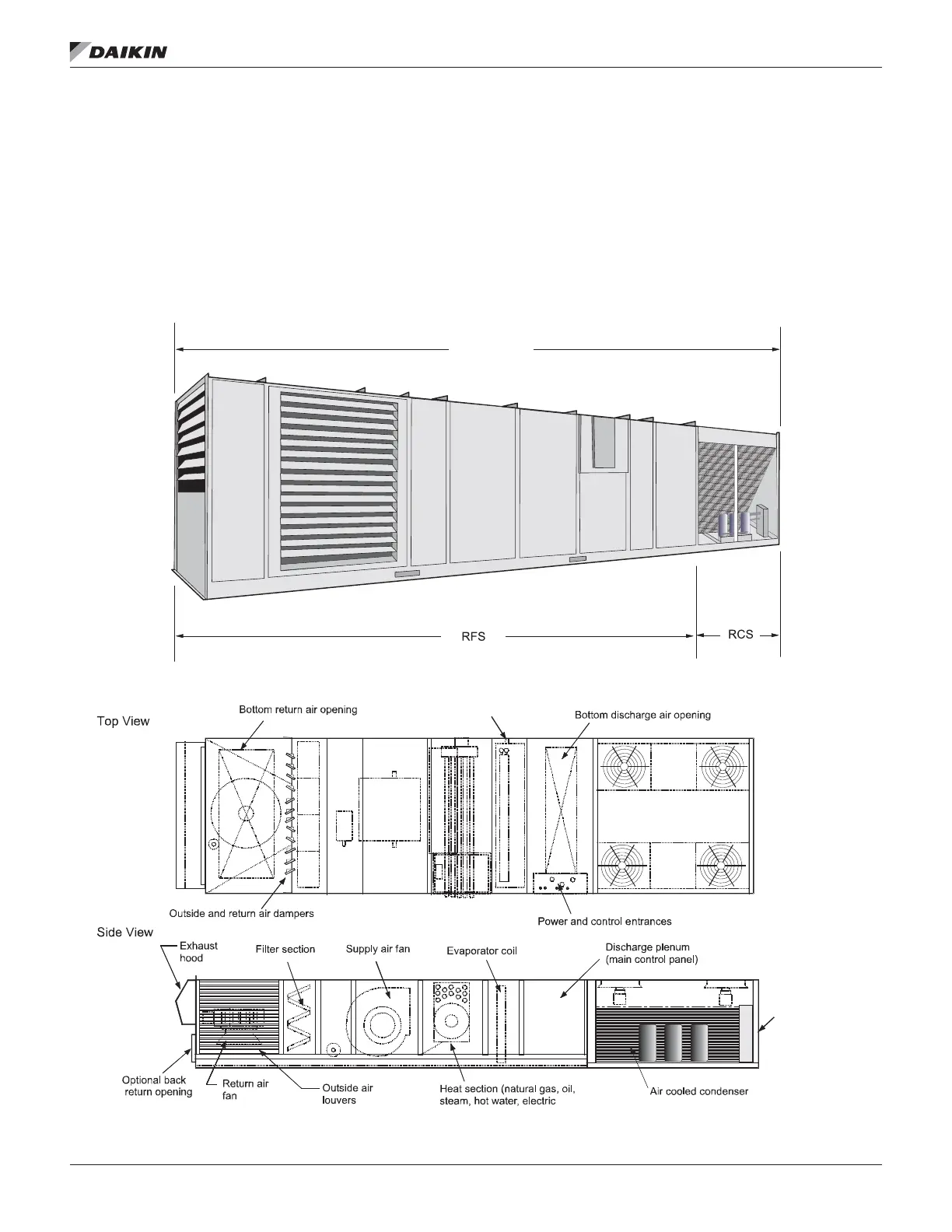
Figure 2 shows an RPS/RDT/RFS/RCS unit. Figure 3 shows
a typical RPS unit with the locations of the major components.
Figure 4 shows a typical RDT unit with the locations of the
major components. These gures are for general information
only. See the project’s certied submittals for actual specic
dimensions and locations.
Figure 2: RPS/RDT/RFS/RCS Unit
Figure 3: Typical Component Locations—RPS Units
RPS/RDT
1.5" NPT Drain
Condenser
control panel
(RCS only)
 Loading...