

J
jasondiazSep 8, 2025
How to fix Daikin Air Conditioner operation that does not start soon?
- AAshley PowellSep 8, 2025
If your Daikin Air Conditioner operation does not start soon, you should wait for about 3 minutes.
How to fix Daikin Air Conditioner operation that does not start soon?
If your Daikin Air Conditioner operation does not start soon, you should wait for about 3 minutes.
Why hot air does not flow out soon after starting heating operation on my Daikin RK35BVMB Air Conditioner?
If hot air does not flow out soon after you start the heating operation on your Daikin air conditioner, you should wait for 1 to 4 minutes.
What to do if my Daikin RK35BVMB Air Conditioner does not operate and the OPERATION lamp is off?
If your Daikin air conditioner isn't operating and the OPERATION lamp is off, check these items: * Confirm that a breaker hasn’t turned OFF or a fuse blown. * Check for a power failure. * Ensure batteries are properly set in the remote controller. * Verify that the timer setting is correct.
What to do if an abnormal functioning happens during Daikin Air Conditioner operation?
If an abnormal functioning occurs during operation of your Daikin air conditioner, turn the breaker OFF, then turn it back ON, and try operating the air conditioner with the remote controller.
Why did my Daikin RK35BVMB operation stopped suddenly but the OPERATION lamp is on?
If your Daikin air conditioner operation stopped suddenly but the OPERATION lamp is on, it automatically resumes operation in about 3 minutes.
| Cooling Capacity | 3.5 kW |
|---|---|
| Heating Capacity | 4.0 kW |
| Refrigerant | R32 |
| Power Supply | 220-240 V, 50 Hz |
| Indoor Unit Weight | 9 kg |
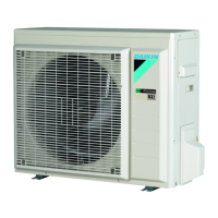
| Outdoor Unit Weight | 32 kg |
Overview of available functions for different models.
Lists functions applicable to cooling-only models.
Lists functions applicable to heat pump models.
Technical details and operating parameters of the units.
Technical specifications for cooling-only units.
Technical specifications for heat pump units.
Diagrams showing PCB connectors and their assignments.
PCB connector layout and function for indoor units.
PCB connector layout and function for outdoor units.
Detailed explanation of core operational functions.
How compressor frequency controls capacity and performance.
Describes airflow control features like flaps and louvers.
How fan speed is adjusted based on operating conditions.
Explains humidity control while maintaining room temperature.
Describes automatic mode switching between cooling and heating.
Mode for energy saving during sleep by adjusting temperature.
Function using a motion sensor for energy saving.
Function to record and recall preferred operating settings for convenience.
Maximizes cooling/heating output by increasing fan and compressor speed.
Covers miscellaneous functions like Hot Start.
Explanation of key components and their roles.
Illustrates the basic refrigeration cycle components.
Explains the role of various thermistors in system control.
Details the logic and parameters for unit operation control.
Outlines the priority of different operating modes.
Details how compressor frequency is determined and adjusted.
Describes operations during mode changes and unit startup.
Explains control logic based on discharge pipe temperature.
Details setting frequency limits based on input current.
Explains how freezing of the indoor heat exchanger is prevented.
Describes controls to limit heating output during peak demand.
Details fan control logic based on various operating conditions.
Protects compressor by limiting output frequency based on temperature.
Compressor stop logic based on outdoor temperature conditions.
Explains the defrosting cycle for heat pump models.
Details control strategies for the electronic expansion valve.
Lists and explains various detected malfunctions and their codes.
Describes the forced cooling mode used for service.
Covers supplementary functions like Voltage Detection.
Guidance on proper unit operation and user explanation.
Important instructions for safe installation and operation.
Essential safety guidelines for installation and unit handling.
Identification of key components in the indoor and outdoor units.
Steps for setting up the remote controller and initial unit preparation.
Explains how to select and change the unit's operating modes.
Instructions for adjusting horizontal and vertical louvers for airflow.
How to activate and use the powerful mode for maximum output.
Lowers outdoor unit noise level for quiet operation, especially at night.
Function to record and recall preferred operating settings for convenience.
Explains the motion sensor function for energy saving.
How to set timers for automatic ON/OFF operation of the unit.
Procedures for cleaning the indoor unit, outdoor unit, and filters.
Guide to identifying and resolving common operational problems.
Important warnings and guidelines before performing diagnostic checks.
Lists common operational issues and their corresponding checks and measures.
Describes how to access diagnostic error codes via the remote controller.
Comprehensive guide to diagnosing and resolving unit malfunctions.
Table of error codes, their meanings, and reference pages.
Troubleshooting steps for faults related to the indoor unit's PCB.
Explains conditions leading to freeze-up or high-pressure faults.
Troubleshooting steps for issues with the fan motor or related components.
Troubleshooting steps for indoor thermistor faults or abnormalities.
Diagnosing communication errors between the indoor and outdoor units.
Troubleshooting steps for compressor overload conditions.
Troubleshooting steps for compressor lock faults.
Diagnosing faults related to excessive input current detection.
Troubleshooting steps for four-way valve malfunctions.
Explains control logic and troubleshooting for discharge pipe temperature.
Troubleshooting for compressor startup failure related to position sensor.
Diagnosing faults related to the Current Transformer (CT) sensor.
Troubleshooting steps for outdoor unit thermistor faults.
Diagnosing issues related to temperature rise in the electrical box.
Troubleshooting for faults related to radiation fin temperature.
Diagnosing faults related to output over-current detection.
Explains detection and troubleshooting for insufficient refrigerant gas.
Troubleshooting steps for over-voltage conditions.
Diagnosing issues related to high pressure in cooling mode.
Procedures for checking specific components and systems.
General guidance on performing component checks.
Procedure to check the electronic expansion valve's function.
Procedures for disassembling the indoor unit components.
Step-by-step guide to remove and replace the air filter.
Procedure to remove and reattach the front grille assembly.
Instructions for removing internal air direction blades.
Steps to access and remove internal electronic components.
Detailed procedure for removing the indoor unit's heat exchanger.
Instructions for installing the drain plug correctly during assembly.
Steps to remove the indoor unit's fan motor and rotor.
Procedures for disassembling the outdoor unit components.
Steps to remove the outer panels and covers of the outdoor unit.
Procedure to remove the bell mouth and side panel of the fan assembly.
Steps to access and remove the outdoor unit's main PCB and electrical box.
Procedure to remove the outdoor unit's fan motor and propeller.
Steps to remove the noise absorption pad for the compressor.
Instructions for removing internal partition plates and reactors.
Detailed procedure for removing the four-way valve and its motor.
Steps for safely removing the main compressor unit.
Additional information and settings not covered elsewhere.
Configuration options for jumpers and addresses for dual units.
Setting addresses for multiple indoor units in one room.
Details the functions of PCB jumpers JC and JB.
How to adjust the sensor angle for optimal detection range.
General explanations and notes on unit operation.
Guide to performing trial operation using the remote controller.
Diagrams illustrating refrigerant piping configurations.
Diagram showing refrigerant piping for indoor units.
Diagrams showing refrigerant piping for outdoor units.
Diagrams showing electrical connections and layouts.
Wiring diagrams for indoor unit PCBs and components.
Wiring diagrams for outdoor unit PCBs and components.