Do you have a question about the Daikin RKS36LVJU and is the answer not in the manual?
Important safety precautions for performing repair work on the unit, covering electrical hazards, refrigerant handling, and personal protective equipment.
User-specific safety advice to prevent electrical shock, fire, and equipment damage during operation and maintenance.
Overview of functions available for the FTXS Series indoor and outdoor units, categorized by feature.
Overview of functions available for the FDXS Series indoor and outdoor units, categorized by feature.
Detailed technical specifications for FTXS Series indoor and outdoor units, including capacity, power, dimensions, and sound levels.
Detailed technical specifications for FDXS Series indoor and outdoor units, including capacity, power, dimensions, and sound levels.
Wiring diagrams and connector details for FTXS and FDXS indoor units, covering control, receiver, display, and sensor PCBs.
Wiring diagrams and connector details for RXS and RKS outdoor units, covering filter, main, and operation button PCBs.
Explains core operational functions like temperature control, frequency principles, airflow, and special modes like ECONO and POWERFUL.
Details control logic, protection mechanisms, frequency control, and potential malfunctions/errors for the system.
Guides for post-installation operation, user manual explanations, and efficient use of the air conditioning system.
Explains remote controller functions, various operating modes (AUTO, DRY, COOL, HEAT, FAN), and special features for the FTXS Series.
Explains remote controller functions, various operating modes (AUTO, DRY, COOL, HEAT, FAN), and special features for the FDXS Series.
Covers LED indicators, common problem symptoms, service check functions, and detailed error code diagnostics.
Outlines checks for specific components such as thermistors, fan motors, PCBs, and electrical parts as part of troubleshooting.
Step-by-step instructions for disassembling FTXS (09/12, 15/18/24, 30/36LVJU) indoor units, covering filters, panels, motors, PCBs, etc.
Step-by-step instructions for disassembling RXS (09/12, 15/18, 24LVJU) and RKS/RXS (30/36LVJU) outdoor units, covering panels, motors, PCBs, etc.
Procedures for pump down, forced cooling, and trial operation to ensure correct system function after installation.
Details on setting model type, temperature display, room configuration, facility settings, and jumper configurations.
Instructions for applying silicon grease to power transistors and diode bridges on outdoor unit PCBs for proper heat radiation.
Visual representations of refrigerant piping configurations for indoor and outdoor units, detailing connections and component locations.
Electrical wiring schematics for indoor and outdoor units, showing connections between components and PCBs for troubleshooting.
Warnings regarding product corrosion, specifically about installation locations and corrosive environments.
| Cooling Capacity | 3.6 kW |
|---|---|
| Refrigerant | R32 |
| Indoor Unit Dimensions (W x H x D) | 283 x 770 x 223 mm |
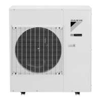
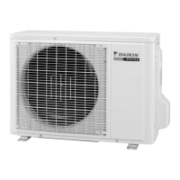
| Outdoor Unit Dimensions (W x H x D) | 550 x 765 x 285 mm |
| Weight (Indoor Unit) | 8 kg |
| Weight (Outdoor Unit) | 30 kg |
| Wall Mounted | Yes |
| Heating Capacity | 4.0 kW |
| Indoor Unit Weight | 8 kg |
| Outdoor Unit Weight | 30 kg |
| Type | Split System |
| Star Rating | 5 |
| Power Supply | 220-240V/50Hz |