Home
Daikin
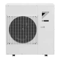
Air Conditioner
RKS30HVJU
Daikin RKS30HVJU - User Manual
202 pages
Manual
Specs
Ask a question
Save Page as PDF
To Next Page
To Next Page
Loading...
Service
Manual
Inverter Pair
Wall Mounted Type H-Series
SiUS04-924_A
[Applied Models]
Inverter Pair : Cooling Only
Inverter Pair : Heat Pump
2
Table of Contents
Main Page
Table of Contents
2
Safety Considerations
7
List of Functions
9
Functions
10
Specifications
11
Specifications
12
Cooling Only / 60 Hz, 208 - 230 V
12
Heat Pump / 60 Hz, 208 - 230 V
13
Printed Circuit Board Connector Wiring Diagram6
15
Indoor Unit
15
Outdoor Unit
18
Function and Control12
20
Main Functions
21
Temperature Control
21
Frequency Principle
21
Airflow Direction Control
23
Fan Speed Control for Indoor Unit
25
Program Dry Operation
26
Automatic Operation
27
Thermostat Control
28
NIGHT SET Mode
29
ECONO Operation
30
INTELLIGENT EYE Operation
31
Inverter POWERFUL Operation
32
Other Functions
33
Function of Thermistor
34
Control Specification
35
Mode Hierarchy
35
Frequency Control
36
Controls at Mode Changing / Start-Up
38
Discharge Pipe Temperature Control
40
Input Current Control
41
Freeze-Up Protection Control
42
Heating Peak-Cut Control
42
Outdoor Fan Control
43
Liquid Compression Protection Function
43
Defrost Control
44
Electronic Expansion Valve Control
45
Malfunctions
48
Operation Manual
49
System Configuration
50
Operation Manual
51
Remote Controller
51
AUTO · DRY · COOL · HEAT · FAN Operation
53
Adjusting the Airflow Direction
55
COMFORT AIRFLOW Operation
57
INTELLIGENT EYE Operation
58
POWERFUL Operation
60
OUTDOOR UNIT QUIET Operation
61
ECONO Operation
62
TIMER Operation
63
WEEKLY TIMER Operation
65
Service Diagnosis
72
Troubleshooting with LED
74
Indoor Unit
74
Outdoor Unit
74
Problem Symptoms and Measures
75
Service Check Function
76
Troubleshooting
79
Error Codes and Description
79
Indoor Unit PCB Abnormality
80
Freeze-Up Protection Control or Heating Peak-Cut Control
81
Fan Motor (DC Motor) or Related Abnormality
83
Thermistor or Related Abnormality (Indoor Unit)
85
Signal Transmission Error (between Indoor Unit and Outdoor Unit)
86
Unspecified Voltage (between Indoor Unit and Outdoor Unit)
88
Outdoor Unit PCB Abnormality
89
OL Activation (Compressor Overload)
90
Compressor Lock
91
DC Fan Lock
92
Input Overcurrent Detection
93
Four Way Valve Abnormality
94
Discharge Pipe Temperature Control
96
High Pressure Control in Cooling
97
Compressor System Sensor Abnormality
99
Position Sensor Abnormality
101
CT or Related Abnormality
103
Thermistor or Related Abnormality (Outdoor Unit)
105
Electrical Box Temperature Rise
107
Radiation Fin Temperature Rise
109
Output Overcurrent Detection
111
Refrigerant Shortage
113
Low-Voltage Detection or Over-Voltage Detection
115
Signal Transmission Error on Outdoor Unit PCB
117
Check
118
Thermistor Resistance Check
118
Fan Motor Connector Output Check
119
Power Supply Waveforms Check
119
Electronic Expansion Valve Check
120
Four Way Valve Performance Check
121
Four-Way Valve Performance Check
121
Inverter Unit Refrigerant System Check
121
Inverter Checker" Check
122
Rotation Pulse Check on the Outdoor Unit PCB
124
Installation Condition Check
125
Discharge Pressure Check
126
Outdoor Fan System Check
126
Capacitor Voltage Check
127
Power Module Check
127
Removal Procedure
128
Indoor Unit
129
Removal of Air Filters / Front Panel
129
Removal of Front Grille
132
Removal of Electrical Box
135
Removal of Pcbs
141
Removal of Horizontal Blades / Vertical Blades / Swing Motors
148
Removal of Fan Motor
156
Removal of Indoor Heat Exchanger
159
Removal of Fan Rotor
162
Outdoor Unit
164
Removal of Outer Panels
164
Removal of Electrical Box
174
Removal of Pcbs
178
Removal of Fan Motor
181
Removal of Coils / Thermistors
182
Removal of Sound Blankets
185
Removal of Compressor
187
Trial Operation and Field Settings
189
Pump down Operation
190
Forced Cooling Operation
191
Trial Operation
192
Field Settings
193
Model Type Setting
193
Temperature Display Switch
193
When 2 Units Are Installed in 1 Room
194
Facility Setting Switch (Cooling at Low Outdoor Temperature)
195
Jumper and Switch Settings
195
Application of Silicon Grease to a Power Transistor and a Diode Bridge188
196
Appendix
197
Piping Diagrams
198
Indoor Unit
198
Outdoor Unit
199
Wiring Diagrams
200
Other manuals for Daikin RKS30HVJU
Service Manual Removal Procedure
38 pages
Need help?
Do you have a question about the Daikin RKS30HVJU and is the answer not in the manual?
Ask a question
Daikin RKS30HVJU Specifications
Print Specification
General
Type
Split System
Power Supply
220-240V, 50Hz
Refrigerant
R32
Noise Level (Indoor Unit)
dB(A)
Noise Level (Outdoor Unit)
dB(A)
Related product manuals
Daikin RKS30LVJU
414 pages
Daikin RKS36LVJU
414 pages
Daikin RKS35BVMB
201 pages
Daikin RKS35CVMB
14 pages
Daikin RKS35E2V1B
232 pages
Daikin RKS35G2V1B
316 pages
Daikin RKS35D2VMB
228 pages
Daikin RKS35D3VMB
228 pages
Daikin RKS35J2V1B
268 pages
Daikin RKS35F2V1B
283 pages
Daikin RKS35G2V1B9
316 pages
Daikin RKS25LVMA
248 pages