Do you have a question about the Daikin RKS42J2V1B and is the answer not in the manual?
Product designation and model series for the Daikin air conditioner service manual.
Detailed technical specifications for cooling-only operation models.
Detailed technical specifications for heat pump operation models.
Essential safety warnings, precautions, and guidelines for handling and repairing the air conditioner.
Common operational problems and their corresponding solutions or checks.
Detailed guide to diagnosing and resolving common error codes and system abnormalities.
List of error codes displayed by the system with their meanings and reference pages.
Troubleshooting steps for indoor unit PCB malfunction.
Diagnosis and troubleshooting procedures for fan motor issues.
Steps to diagnose thermistor failures in the indoor unit.
Troubleshooting guide for communication errors between indoor and outdoor units.
Troubleshooting steps for outdoor unit PCB malfunctions.
Diagnostic procedures for compressor lock errors.
Methods for detecting and diagnosing refrigerant shortage issues.
Step-by-step instructions for removing internal components of the indoor unit.
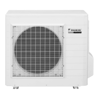
Procedures for disassembling the RK(X)S20/25/35J2V1B outdoor unit.
Steps to remove outer panels and the fan motor assembly.
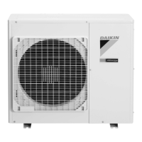
Procedures for disassembling the RK(X)S42J2V1B outdoor unit.
Instructions for removing PCBs from the RK(X)S42J2V1B outdoor unit.
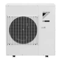
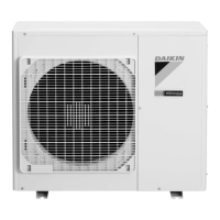
Procedures for disassembling the RK(X)S50J2V1B outdoor unit.
Steps to remove the outer panels of the RK(X)S50J2V1B outdoor unit.
Procedure for removing the electrical box from the RK(X)S50J2V1B outdoor unit.
Instructions for removing PCBs from the RK(X)S50J2V1B outdoor unit.
Instructions for removing the four-way reversing valve.
Detailed steps for safely removing the compressor from the RK(X)S50J2V1B unit.
| Model | RKS42J2V1B |
|---|---|
| Brand | Daikin |
| Category | Air Conditioner |
| Type | Split System |
| Cooling Capacity | 4.2 kW |
| Energy Efficiency Ratio (EER) | 3.21 |
| Energy Efficiency Ratio (Cooling) | 3.21 |
| Power Supply | 220-240V, 50Hz |
| Refrigerant | R32 |
| Weight (Indoor Unit) | 9 kg |
| Outdoor Unit Noise Level | 48 dB(A) |
| Power Consumption Cooling | 1.31 kW |
| Outdoor Unit Dimensions (HxWxD) | 550 x 780 x 285 mm |