Do you have a question about the Daikin RXS20K2V1B and is the answer not in the manual?
Covers warnings and cautions for safe repair and operation, including pictograms.
Explains the meaning of various icons used throughout the manual for clarity.
Lists and describes all operational functions of the air conditioner system.
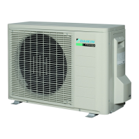
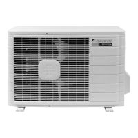
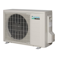
Provides detailed technical data and specifications for the indoor and outdoor units.
Illustrates PCB component layout and connector assignments for the indoor unit.
Illustrates PCB component layout and connector assignments for the outdoor unit.
Explains primary operational functions like temperature, airflow, and mode controls.
Explains how the system controls room temperature based on sensor readings.
Details the inverter's variable frequency operation for compressor speed control.
Describes how airflow direction is managed for user comfort and distribution.
Outlines the automatic and manual fan speed settings for the indoor unit.
Explains the dry mode function for humidity removal while maintaining temperature.
Describes the system's ability to automatically switch between cooling and heating modes.
Details the thermostat's operation based on temperature differences and zones.
Explains the mode that adjusts temperature for comfortable sleep and energy saving.
Describes the energy-saving mode that limits maximum power consumption.
Explains the sensor-based function that saves energy when the room is unoccupied.
Details the mode that maximizes cooling/heating capacity by increasing fan and compressor speed.
Covers additional functions like Hot-Start and Timer operations.
Explains the role of thermistors in monitoring temperatures for system control.
Outlines the system's operational modes and control logic for various conditions.
Identifies parts of the remote controller and basic operation.
Guides on using AUTO, DRY, COOL, HEAT, and FAN modes for optimal comfort.
Uses LED indicators to identify and diagnose system errors and malfunctions.
Lists common issues and provides corresponding troubleshooting steps.
Explains how to access the service check mode via the remote controller for diagnosis.
Comprehensive guide to diagnosing and resolving various system errors and faults.
Detailed steps for checking specific components like thermistors, motors, and PCBs.
Step-by-step instructions for safely disassembling and removing indoor unit parts.
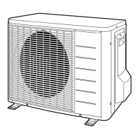
Step-by-step instructions for safely disassembling and removing outdoor unit parts.
Procedures for verifying system performance and settings after installation.
Details on configuring system settings like model type and jumpers for specific environments.
Visual representation of the refrigerant pipe connections for both units.
Electrical schematics illustrating the internal wiring of the units.
| Cooling Capacity | 2.0 kW |
|---|---|
| Heating Capacity | 2.5 kW |
| Energy Efficiency Ratio (EER) | 3.21 |
| Power Supply | 230V/1Ph/50Hz |
| Refrigerant | R32 |
| Indoor Unit Dimensions (W x H x D) | 800 x 290 x 215 mm |
| Outdoor Unit Dimensions (W x H x D) | 800 x 550 x 285 mm |
| EER | 3.21 |
| Energy Efficiency Ratio (Cooling) | 3.21 |
| Power Consumption Cooling | 0.62 kW |
| Indoor Unit Noise Level | 19 dB |