8 Finishing the outdoor unit installation
Installation manual
15
RXTM30+40N2V1B + RXTP25+35N2V1B9 +
RXTP25+35N2V1B8 + ARXTP25+35N2V1B + RXTA30N2V1B
R32 split series
3P482320-10S – 2020.08
WARNING
▪ Do NOT use locally purchased electrical parts inside
the product.
▪ Do NOT branch the power supply for the drain pump,
etc. from the terminal block. This could result in
electrical shock or fire.
WARNING
Keep the interconnection wiring away from copper pipes
without thermal insulation as such pipes will be very hot.
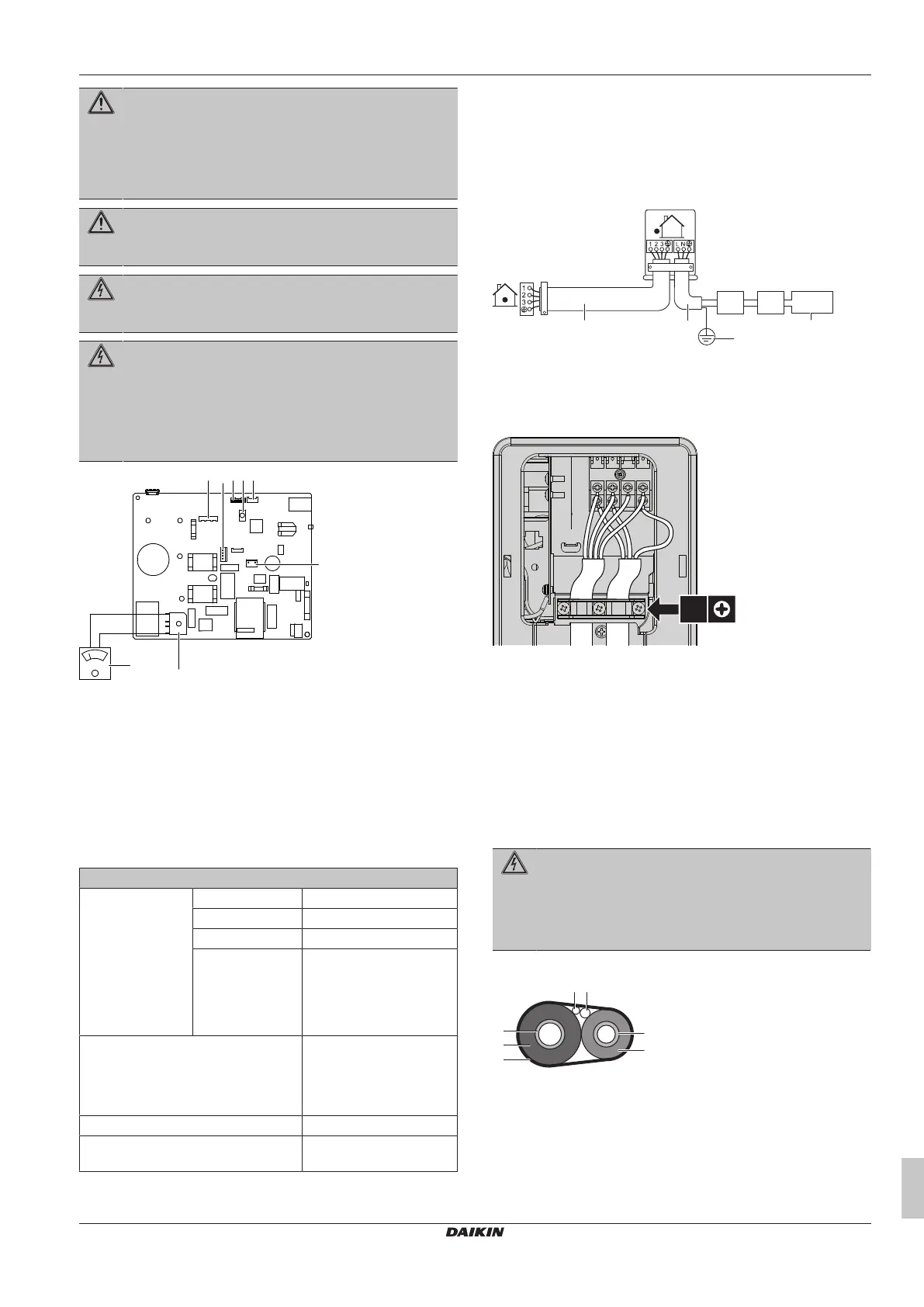
DANGER: RISK OF ELECTROCUTION
All electrical parts (including thermistors) are powered by
the power supply. Do not touch them with bare hands.
DANGER: RISK OF ELECTROCUTION
Disconnect the power supply for more than 10 minutes,
and measure the voltage at the terminals of main circuit
capacitors or electrical components before servicing. The
voltage MUST be less than 50VDC before you can touch
electrical components. For the location of the terminals,
see the wiring diagram.
a Multimeter (DC voltage range)
b S80 – reversing solenoid valve lead wire
c S70 – fan motor lead wire
d LED
e S90 – thermistor lead wire
f S20 – electronic expansion valve lead wire
g S40 – thermal overload relay lead wire
h DB1 - diode bridge
7.1 Specifications of standard wiring
components
Component
Power supply cable Voltage 220~240V
Phase 1~
Frequency 50Hz
Wire sizes 3-core cable
2.5mm
2(a)(b)
/ 4.0 mm
2(b)
(a)
H05RN-F (60245 IEC 57)
(b)
H07RN-F (60245 IEC 66)
Interconnection cable
(indoor↔outdoor)
4-core cable
1.5mm
2
~2.5mm
2
and
applicable for 220~240V
H05RN-F (60245 IEC 57)
Recommended circuit breaker 16A
Residual current device MUST comply with
applicable legislation
7.2 To connect the electrical wiring to
the outdoor unit
1 Remove the service cover.
2 Open the wire clamp.
3 Connect the interconnection cable and power supply as follows:
a Interconnection cable
b Power supply cable
c Circuit breaker
d Residual current device
e Power supply
f Earth
4 Tighten the terminal screws securely. We recommend using a
Phillips screwdriver.
8 Finishing the outdoor unit
installation
8.1 To finish the outdoor unit
installation
DANGER: RISK OF ELECTROCUTION
▪ Make sure that the system is earthed properly.
▪ Turn off the power supply before servicing.
▪ Install the service cover before turning on the power
supply.
1 Insulate and fix the refrigerant piping and cables as follows:
a Gas pipe
b Gas pipe insulation
c Interconnection cable
d Field wiring (if applicable)
e Liquid pipe
f Liquid pipe insulation
g Finishing tape
2 Install the service cover.
 Loading...