9 Configuration
Installation manual
16
RXTM30+40N2V1B + RXTP25+35N2V1B9 +
RXTP25+35N2V1B8 + ARXTP25+35N2V1B + RXTA30N2V1B
R32 split series
3P482320-10S – 2020.08
9 Configuration
9.1 Facility setting
Use this function for cooling at low outdoor temperature. This
function is designed for facilities such as equipment of computer
rooms. NEVER use in a residence or office where people occupy the
space.
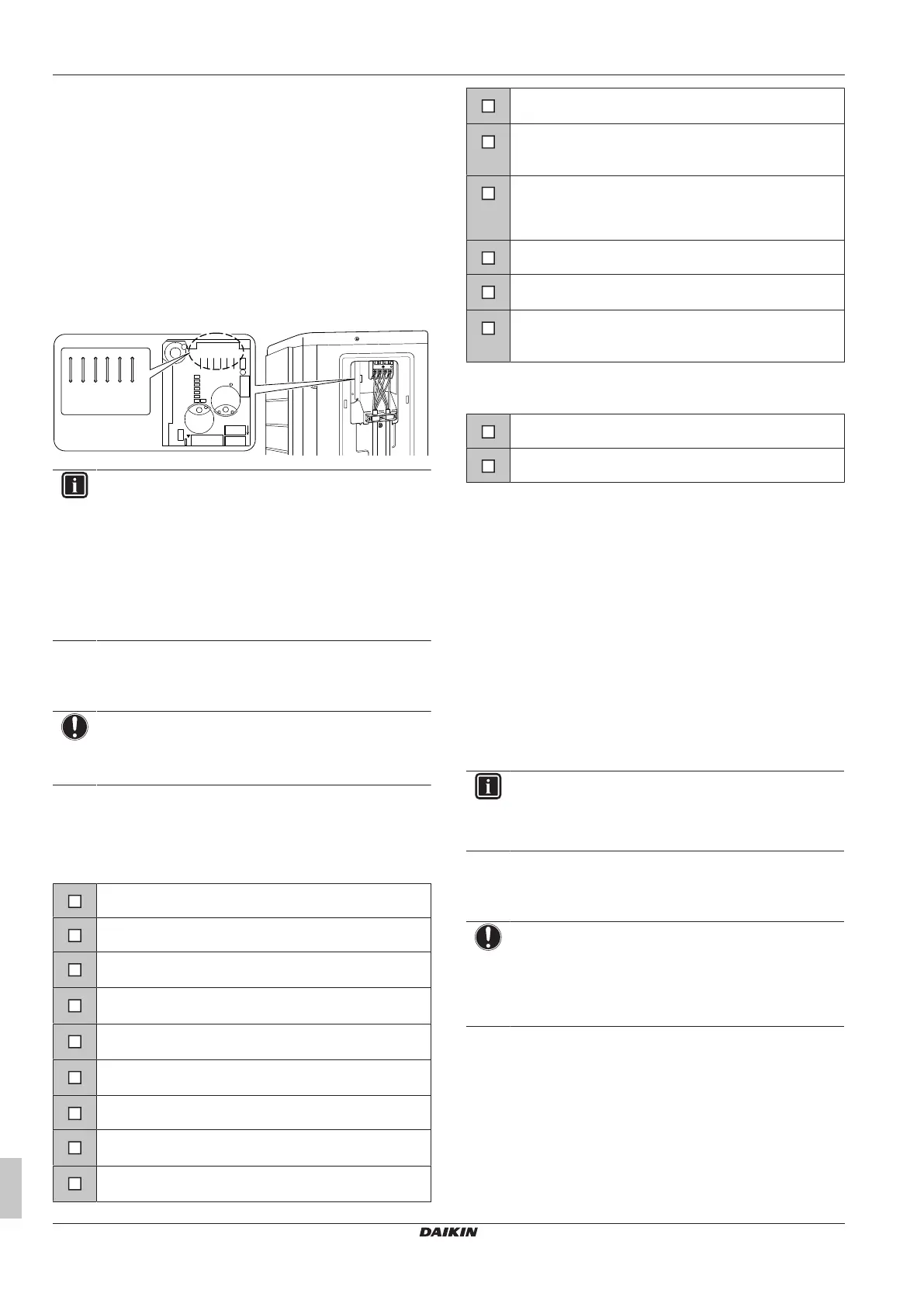
9.1.1 To set the facility mode
When cutting jumper J6 on the PCB, the operation range will expand
to –15°C. The facility mode will stop if the outdoor temperature drops
below –20°C and resume when the temperature rises again.
1
2
3
J5
J6
J8
J9
J11
J12
+6V
R714
R713
R712
R711
R710
R721
R612
R613
D204
D202
C207
D203
ID201
C211
D206
J12
J11
J9
J8
J6
J5
INFORMATION
▪ The indoor unit may produce Intermittent noise due to
the outdoor unit fan turning ON and/or OFF.
▪ Do NOT place humidifiers or other items which might
raise humidity in rooms when you use the facility mode.
▪ Cutting jumper J6 sets the indoor unit fan to the highest
speed.
▪ Do NOT use this setting in residences or offices with
people.
10 Commissioning
NOTICE
ALWAYS operate the unit with thermistors and/or pressure
sensors/switches. If NOT, burning of the compressor might
be the result.
10.1 Checklist before commissioning
After the installation of the unit, first check the items listed below.
Once all checks are fulfilled, the unit must be closed. Power-up the
unit after it is closed.
The indoor unit is properly mounted.
The outdoor unit is properly mounted.
The system is properly earthed and the earth terminals
are tightened.
The power supply voltage matches the voltage on the
identification label of the unit.
There are NO loose connections or damaged electrical
components in the switchbox.
There are NO damaged components or squeezed
pipes on the inside of the indoor and outdoor units.
There are NO refrigerant leaks.
The refrigerant pipes (gas and liquid) are thermally
insulated.
The correct pipe size is installed and the pipes are
properly insulated.
The stop valves (gas and liquid) on the outdoor unit are
fully open.
The following field wiring has been carried out according
to this document and the applicable legislation between
the outdoor unit and the indoor unit.
Drainage
Make sure drainage flows smoothly.
Possible consequence: Condensate water might drip.
The indoor unit receives the signals of the user interface.
The specified wires are used for the interconnection
cable.
The fuses, circuit breakers, or locally installed protection
devices are installed according to this document, and
have NOT been bypassed.
10.2 Checklist during commissioning
To perform an air purge.
To perform a test run.
10.3 To perform a test run
Prerequisite: Power supply MUST be in the specified range.
Prerequisite: Test run may be performed in cooling or heating
mode.
Prerequisite: Test run should be performed in accordance with the
operation manual of the indoor unit to make sure that all functions
and parts are working properly.
1 In cooling mode, select the lowest programmable temperature.
In heating mode, select the highest programmable temperature.
Test run can be disabled if necessary.
2 When the test run is finished, set the temperature to a normal
level. In cooling mode: 26~28°C, in heating mode: 20~24°C.
3 The system stops operating 3 minutes after the unit is turned
OFF.
INFORMATION
▪ Even if the unit is turned OFF, it consumes electricity.
▪ When the power turns back on after a power break, the
previously selected mode will be resumed.
11 Disposal
NOTICE
Do NOT try to dismantle the system yourself: dismantling
of the system, treatment of the refrigerant, oil and other
parts MUST comply with applicable legislation. Units
MUST be treated at a specialised treatment facility for
reuse, recycling and recovery.
12 Technical data
▪ A subset of the latest technical data is available on the regional
Daikin website (publicly accessible).
▪ The full set of latest technical data is available on the Daikin
Business Portal (authentication required).
 Loading...