Do you have a question about the Daikin RXYSQ4-5-6PA7V1B and is the answer not in the manual?
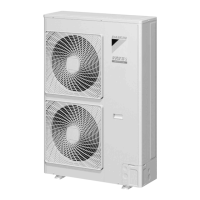
Detailed technical specifications for outdoor units, including capacity, COP, dimensions, and operating ranges.
Technical specifications for various indoor unit types, such as cassette, duct, and wall-mounted units.
Component list for various indoor units, covering remote controllers, motors, thermistors, and other parts.
Diagram and description of the outdoor unit's refrigerant circuit, listing components and their major functions.
Illustrates the functional parts layout for outdoor units, showing component locations and connections.
Explains the different operation modes of the system, including normal, standby, and protection states.
Step-by-step guide for initial test operation, covering power supply checks, refrigerant charging, and airtightness.
Details operations when power is first turned on, including initial setup and subsequent power-on procedures.
Guides on changing individual indoor unit functions using wired and wireless remote controllers.
Explains field settings made via dip switches on the outdoor unit's PC board.
Troubleshooting guide based on observed symptoms, providing supposed causes and countermeasures.
Diagnoses and resolves issues related to the 'A0' error code for external protection devices in indoor units.
Troubleshooting steps for 'A1' error code indicating a defective indoor unit PC board.
Addresses 'A3' error code related to the drain level control system malfunction in indoor units.
Troubleshooting for 'A6' error code indicating fan motor lock or overload in indoor units.
Guidance for 'A7' error code related to swing flap motor malfunction in indoor units.
Troubleshooting for 'A8' error code indicating abnormal power supply voltage.
Steps to resolve 'A9' error for malfunction of the moving part of the electronic expansion valve.
Troubleshooting for 'AF' error code indicating the drain level is above the limit in indoor units.
Addresses 'AJ' error code for malfunction of the capacity determination device in indoor units.
Resolves 'C1' error for transmission failure between indoor unit PC board and fan PC board.
Troubleshooting for 'C4' error indicating thermistor malfunction for the heat exchanger.
Addresses 'C5' error for thermistor malfunction on gas pipes in indoor units.
Resolves 'C6' error for failure of combination between indoor PC board and fan PC board.
Troubleshooting for 'C9' error indicating thermistor malfunction for suction air.
Addresses 'CA' error for thermistor malfunction for discharge air in indoor units.
Troubleshooting for 'CC' error indicating malfunction of the humidity sensor system.
Resolves 'CJ' error for malfunction of the thermostat sensor in the remote controller.
Diagnoses 'E1' error for a defective outdoor unit PC board.
