Installation manual
3
R(Y)(P)71~125B7
Split System air conditioners
4PW10931-1B
I
NSTALLATION
SERVICING
SPACE
The numerical figures used herein represent the dimensions for the
models R(Y)(P)71 to 125. Figures in ( ) indicate the dimensions for
the models R(Y)(P)100 and 125. (Unit: mm)
(Refer to "Precautions on installation" on page 2)
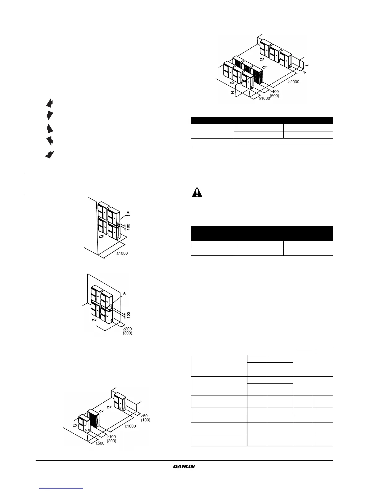
Precaution
When installing link of multiple outdoor units, leave a space of
200 mm or more between the casing of one unit and the stop valves
of the other unit.
(A) In case of non-stacked installation
(See figure 1)
(B) In case of stacked installation
1.
In case obstacles exist in front of the outlet side.
2.
In case obstacles exist in front of the air inlet.
Do not stack more than one unit.
About 100 mm is required as the dimension for laying the upper
outdoor unit's drain pipe. Get the portion A sealed so that air from the
outlet does not bypass.
(C) In case of multiple-row installation (for roof top use, etc.)
1.
In case of installing one unit per row.
2.
In case of installing multiple units (2 units or more) in lateral
connection per row.
Relation of dimensions of H, A and L are shown in the table below.
R
EFRIGERANT PIPE SIZE AND ALLOWABLE PIPE
LENGTH
1. Refrigerant pipe size
■ Pair system (See figure 2)
■ Simultaneous operation system
■ Twin and triple operation system (twin: see figure 3, triple:
see figure 4)
The pipes between the outdoor unit and the branch (L1) should have
the same size as the outdoor connections. The pipes between the
branch and the indoor units (L2~L4) should have the same size as
the indoor connections. Branch: see marking '■ ' on figures
figure 3~figure 4.
2. Allowable pipe length
See the table below concerning lengths and heights. Refer to
figure 2~figure 4. Assume that the longest line in the figure
corresponds with the actual longest pipe, and the highest unit in the
figure corresponds with the actual highest unit.
Suction side obstacle
Discharge side obstacle
Left side obstacle
Right side obstacle
Top side obstacle
✓
Obstacle is present
L A
L≤H
0 < L ≤ 1/2 H 150 (250)
1/2H < L 200 (300)
H < L Installation impossible
All field piping must be installed by a licensed refrigeration
technician and must comply with relevant local and
national regulations.
Refrigerant pipe size
Gas pipe Liquid pipe
R(Y)(P)71 ø 15.9 x t1.0
ø 9.5 x t0.8
R(Y)(P)100,125 ø 19.1 x t1.0
R407C R22
Maximum allowable piping
length (Parenthesized
figure represents
equivalent length)
Pair L1
70 m
(90 m)
50 m
(70 m)
Twin /
Triple
L1+L2
Maximum total one-way
pipe length
Twin L1+L2+L3
80 m 60 m
Triple
L1+L2+L3
+L4
Maximum branch pipe
length
Twin /
Triple
L2 20 m 20 m
Maximum difference
between branch lengths
Twin L2-L3
10 m 10 m
Triple L2-L4
Maximum height between
indoor and outdoor
All H1 30 m 30 m
Maximum height between
indoors
Twin /
Triple
H2 0.5 m 0.5 m