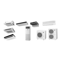
Si-71A
ii Table of Contents
1. Introduction ........................................................................................... vii
1.1 Safety Cautions...................................................................................... vii
3DUW#4 ,PSURYHG#3RLQWV#DQG#)XQFWLRQV 11111111111111111111111111111111111111111 4
1. 1999 New Models Functions...................................................................2
1.1 Cooling Only and Heat Pump...................................................................2
2. Present Model’s Functions......................................................................4
2.1 Cooling Only and Heat Pump...................................................................4
3DUW#5 5HPRWH#&RQWUROOHU#2SHUDWLRQ111111111111111111111111111111111111111111111 <
1. Wired Remote Controller.......................................................................10
1.1 Wired Remote Controller........................................................................10
2. Wireless Remote Controller ..................................................................12
2.1 Wireless Remote Controller ...................................................................12
3. Wireless Remote Controller ..................................................................14
3.1 Wireless Remote Controller ...................................................................14
3DUW#6 ([SODQDWLRQ#RI#)LHOG#6HW1111111111111111111111111111111111111111111111111114:
1. Method of Field Set (Reset after Maintenance Inspection/Repair) .......18
1.1 Explanation.............................................................................................18
1.2 Field Setting ...........................................................................................19
1.3 Initial Setting Contents ...........................................................................21
1.4 Local Setting Mode No...........................................................................22
1.5 Detailed Explanation of Setting Modes ..................................................24
1.6 Centralized Group No. Setting ...............................................................29
2. Settings Concerning Maintenance ........................................................30
2.1 Indoor Unit PCB .....................................................................................30
2.2 Outdoor Unit Switches / Setting Jumper ................................................40
3. Existence of DIP Switch, Jumper and BS .............................................42
3.1 Reference Table.....................................................................................42
3.2 Emergency Operation ............................................................................43
3.3 Maintenance Mode Setting.....................................................................44
3DUW#7 ([SODQDWLRQ#RI#)XQFWLRQ#2SHUDWLRQ1111111111111111111111111111111111 78
1. Function Outline....................................................................................46
1.1 Indoor Unit..............................................................................................46
1.2 Outdoor Unit...........................................................................................48
2. Operation Flowchart (RY71 - 140K)......................................................49
2.1 Cooling/Program Dry Operation.............................................................49
2.2 Heating...................................................................................................51
3. Electric Function Parts..........................................................................53
3.1 Indoor Unit..............................................................................................53
3.2 Outdoor Unit...........................................................................................56
4. Thermistor Temperature and Resistance Conversion Table ................61
4.1 Table ......................................................................................................61
5. Function Details ....................................................................................62
5.1 Indoor Unit..............................................................................................62
5.2 Outdoor Unit...........................................................................................65

 Loading...


