Do you have a question about the Daikin SkyAir Super Inverter 70 D Series and is the answer not in the manual?
| Series | D Series |
|---|---|
| Type | Split System |
| Cooling Capacity | 7.1 kW |
| Heating Capacity | 8.0 kW |
| Coefficient of Performance (COP) | 3.61 |
| Outdoor Unit Noise Level | 50 dB(A) |
| Indoor Unit Weight | 12 kg |
| Power Supply | 220-240V, 50Hz |
| Refrigerant | R410A |
| Indoor Unit Noise Level | 45 dB(A) |
General safety warnings and guidelines for operating and servicing the equipment.
Safety precautions to be observed after performing repairs on the unit.
Procedures for checking the unit's condition after repair work.
Explanation and meaning of icons used in the manual.
Details on model names and their corresponding power supply requirements.
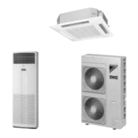
Visual representation of indoor units, remote controllers, and outdoor units.
Detailed breakdown of functions available across various models.
Technical specifications for 50Hz models, including capacity, dimensions, and components.
Technical specifications for 60Hz models, detailing operational parameters and components.
Specifications for models compliant with Australian standards.
Operation and features of the wired remote controller for specific models.
Step-by-step guide for installing the wired remote controller.
Explanation of the wireless remote controller's names and functions.
Essential safety precautions and considerations for refrigerant piping work.
Procedures and guidelines for refrigerant piping installation and charging.
Instructions for electrical wiring between indoor and outdoor units.
Procedure for setting parameters after installation or maintenance.
Settings related to maintenance procedures on unit components.
Table detailing the location and function of DIP switches and jumpers.
Explanation of the roles of key components and thermistors.
Overview of the operational flow for indoor and outdoor units.
List of electrical components used in indoor and outdoor units.
In-depth explanation of various operational functions and controls.
Graphical representation of allowable operating ranges for cooling and heating.
Guidelines for optimal operation conditions and maintenance checks.
Flowchart to diagnose and address customer service requests.
Guide to diagnosing issues based on observed equipment behavior.
Steps for performing self-diagnosis using the remote controller.
Troubleshooting using LED indicators on indoor and outdoor unit PCBs.
Table correlating malfunction codes and LED indicators with issues.
Step-by-step instructions for removing components from FHYCP models.
Procedures for disassembling and removing parts from RZP outdoor units.
Visual diagrams illustrating refrigerant piping configurations.
Electrical wiring schematics for indoor and outdoor units.

