EasyManua.ls Logo

Daikin UWL030B5 User Manual

Daikin UWL030B5
48 pages
To Next Page IconTo Next Page
Page #1 background imageLoading...
Page #1 background image
UWL-B5 Series Water Source
Modular Chiller (Heat Pump)
Catalogue/Engineering Data
Models: UWL030-040B5
Refrigerant: R410A
Cooling Capacity: 118-150kW
Heating Capacity: 130-170kW
ED-UWLB5-1503
ODP=0
R410A
ODP=0
R410A
ODP=0
R410A
ODP=0
R410A
DAIKIN INDUSTRIES., LTD
Question and Answer IconNeed help?

Do you have a question about the Daikin UWL030B5 and is the answer not in the manual?

Daikin UWL030B5 Specifications

General IconGeneral
BrandDaikin
ModelUWL030B5
CategoryHeat Pump
LanguageEnglish

Summary

Model Series

Nomenclature

Features

Water system energy-saving control

Unit optimizes chilled/cooling water pumps and tower based on cooling water temp.

Low carbon and environment friendly

Uses R410A refrigerant for efficient, eco-friendly cooling/heating with heat exchange.

Double backup operation makes double improvement of reliability

Multiple compressors ensure operation even if one fails, enhancing system reliability.

High efficiency shell and tube heat exchanger for condenser and evaporator

Features large pipe diameter & internal thread finned copper tubes for enhanced heat transfer.

Double balance operation extends service life of the overall unit

Balances compressor operation times to reduce failure rates and extend unit life.

Self-protection and self-diagnosis function

Includes over-temp, low-flow, and pressure protections with self-diagnosis capabilities.

Compact and flexible air conditioning solution

Modular design allows easy movement via elevator and installation in existing spaces.

Advanced Features

Rain proof body avoids investment in machine rooms

Rain-proof shell allows outdoor installation, reducing machine room costs and noise.

Easily realize partitioned management

Allows separate control of units in different areas/floors for flexible management.

Multiple cold and heat sources

Supports various sources like geothermal, water, and waste heat for energy saving.

Large capacity unit reduces installation

High capacity single modules reduce installation needs and save space.

Convenient for capacity increase of the system

Easily add units to increase cooling capacity for existing systems.

Trinity function (optional)

Optional heat recovery function for simultaneous heating and hot water generation.

Primary pump variable flow design

Reduces system water flow, saving energy via automatic pump speed adjustment.

Higher efficiency of combining operation

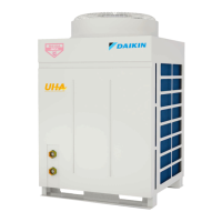
Combines UWL with air-cooled heat pumps for efficient cooling and heating.

Living hot water is made throughout the year

Achieves high hot water temperatures (55°C) for domestic use year-round.

Specifications (General Data)

Components Data

Electrical Data

Safety Devices

Dimensions

Performance Data

Water pressure drop curve

Sound Data (Acoustic Noise)

Wiring Diagram UWL030B5

Wiring Diagram UWL040B5

Installation Working Condition

Installation Dimensions and Environment Limits

Machine Installation Space

Units must be installed by qualified personnel following national/local standards.

Assembling Unit Modules

Details groundwork, mounting bolts, and rubber cushions for module assembly.

Unit Barycenter And Bearing

Space Allocated for A Single Chilled Water Unit

Space Allotted for An Array of Chilled Water Units

Installing chiller

Hoisting chiller

Water system installation

Water quality requirements

Specifies benchmark values for pH, conductivity, and other factors to prevent scale/corrosion.

Connecting Water Pipes

Details requirements for water pumps, gauges, pipes, tanks, and filters.

Installation Illustration Single Unit Water System

Installation Illustration Multi-unit Water System

Installation Illustration Multi-unit Water System Separate Pumps

Cooling/Heating Mode

Hydraulic calculation and pipe system

Pipe design for air-conditioning system

Guidelines for pipe capacity, material, layout, resistance, and energy saving.

Pipe diameter determination

Water Storage Tank Volume Calculating

Water Circulation Pump Selection Principles

Water flow range

Commissioning and Operation

Items to be Confirmed Before Turning on Unit

Pre-start checks including water pump connection, power, and system cleaning.

Items to be Checked during the Pilot Run

Post-operation checks on voltage, current, temperatures, and pressures.

Maintenance (Repair)

Items to be Checked Periodically

Regular checks for heat exchangers, water status, air in system, filters, refrigerant, and lubricant.

Routine Maintenance Schedule

Water Processing Method

Control System Instruction Power Cable Connection

PCB instruction

Illustrates PCB connections for pumps, motors, sensors, and controllers.

Setting up Address Using DIP Switch

Address setting SW3 and SW4

Control Communication Wire Connection

Wired controller instruction Dimensions

Controller Installation

MC305 Controller Functions Features

Use specification

Explains the LCD display elements and button functions for operating the controller.

Controller settings

Setting Parameters

Timer Setting

Error code

Error Code and Running Status

Trouble shooting Wired controller alarm

Trouble shooting Pump and Pressure Errors

Trouble shooting Sensor Malfunctions

Trouble shooting Temperature Sensor Issues

Trouble shooting Low Pressure Sensor Issues

Trouble shooting Refrigerant Leakage and Pressure

Trouble shooting Communication and Setting Errors

Warning

Cautions on product corrosion

Related product manuals