Do you have a question about the Daikin VRV II REYQ16MY1B and is the answer not in the manual?
| Series | VRV II |
|---|---|
| Type | Heat Pump |
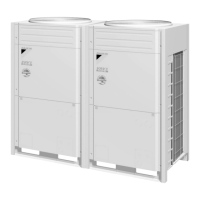
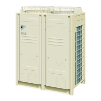
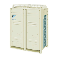
| Outdoor Unit Model | REYQ16MY1B |
| Cooling Capacity (kW) | 16.0 |
| Heating Capacity (kW) | 18.0 |
| Refrigerant | R410A |
| Sound Pressure Level (Outdoor Unit) | 58 dB(A) |
| Power Source | 380-415V / 50Hz / 3Phase |
| Operating Temperature (Cooling) | -5°C to 46°C |
| Indoor Unit Compatibility | Connectable to a wide range of Daikin indoor units (ducted, cassette, wall mounted, etc.) |
Details important safety precautions and pictograms for repair work and general use.
Provides specific warnings for electrical safety, refrigerant handling, and capacitor discharge during repair.
Highlights safety measures for using correct parts, ensuring secure installation, and proper electrical work.
Ensures proper connections, cable integrity, refrigerant system checks, and safe disposal of batteries.
Provides specifications for REYQ48MY1B (combination unit), covering capacity and dimensions.
Lists specifications for FXNQ40MVE to FXNQ63MVE, covering capacity, dimensions, and components.
Details the refrigerant circuit for specific outdoor unit models, including REYQ8, 10, 12M and REYQ14, 16M.
Provides layout diagrams of functional parts for REYQ8, 10, 12M and REYQ14, 16M outdoor units.
Illustrates refrigerant flow diagrams for cooling, heating, and simultaneous operation modes.
Describes solenoid valves (20RT, 20RH) and their functions in the BSVQ refrigerant circuit.
Illustrates the layout of solenoid valves and other functional parts on the plan and front view of REYQ8, 10, 12M.
Illustrates the layout of solenoid valves, fans, and compressors on the plan and front view of REYQ14, 16M.
Shows the placement of various sensors and pressure switches on the plan and front view of REYQ14, 16M.
Explains basic control mechanisms like normal operation, compressor PI control, and fan control.
Details special controls such as startup, oil return, defrosting, and protection controls.
Describes protection mechanisms like high pressure, low pressure, and discharge pipe protection.
Details actuator operations for normal cooling and heating/cooling modes, including compressor and valve control.
Explains compressor capacity PI control for maintaining constant evaporator and condenser temperatures.
Details compressor operating priority tables for REYQ46,48M models, including 50Hz specifications.
Explains PI control for motorized valves EV1, EV2, and EV3 to maintain superheated degrees.
Describes cooling operation fan control based on high pressure detection and fan steps.
Explains heat exchange mode switching for outdoor units (main, sub) into evaporator or condenser based on load.
Details actuator operations for startup control in cooling mode to reduce compressor load and manage four-way valves.
Outlines actuator operations for startup control in heating mode, managing compressor load and four-way valves.
Explains pressure equalization prior to startup to reduce load and manage refrigerant pressure.
Details oil return operation in cooling mode to collect oil from the compressor and prevent machine oil loss.
Describes oil return operation in heating mode to collect oil from the compressor and prevent machine oil loss.
Explains how to use the Inspection/Test Operation button to access various modes for troubleshooting.
Explains how to use the Inspection/Test Operation button to access various modes for troubleshooting.
Details how to use the wired remote controller's self-diagnosis function to identify malfunctions.
Illustrates how the UP and DOWN buttons change the malfunction code digits during self-diagnosis.
Details how to check capacity code, indoor unit system code, indoor unit type code, and outdoor model code.
Details functions within service mode: Malfunction hysteresis, sensor/address data, forced fan, and individual settings.
Explains the self-diagnosis function, using operation lamp, inspection display, and malfunction code to identify issues.
Diagnoses 'UH' error for system malfunction or undefined refrigerant address, checking wiring and PC boards.
Troubleshoots 'MC' error for address duplication or improper setting of centralized controllers.
Troubleshoots 'MC' error for address duplication or improper setting, checking controller connections.
Troubleshoots malfunctions indicated by blinking operation lamps on unified ON/OFF controllers.
Provides troubleshooting steps for blinking operation lamps, checking wiring and PC boards.
Provides troubleshooting steps for single blink display, checking centralized control address and wiring.
Details troubleshooting for double blink display, checking schedule timer connections and PC boards.