Do you have a question about the Daikin VRV III-S RXYMQ6PV4A and is the answer not in the manual?
Details safety precautions, pictograms, and warnings for repair work.
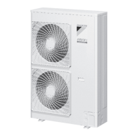
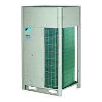
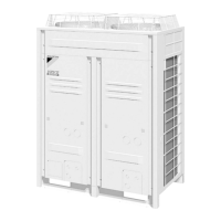
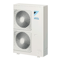
Lists various indoor and outdoor unit models with their specifications.
Visual identification of different indoor and outdoor unit types.
Details the capacity ranges for outdoor and indoor units in HP and capacity index.
Detailed technical specifications for the outdoor unit RXYMQ6PV4A.
Technical specifications for various indoor unit types, including dimensions and performance.
Lists components, symbols, models, and remarks for the outdoor unit.
Lists components, symbols, models, and remarks for various indoor unit types.
Diagram and function of key components in the refrigerant circuit.
Visual layout of functional parts of the RXYMQ6P outdoor unit.
Diagram illustrating system operation modes like normal, standby, and special controls.
Details normal operation controls for cooling and heating modes.
Maintains evaporator outlet superheated degree (SH) and compressor outlet temperature (Tc).
Controls EV for optimal superheated degree in cooling and heating operations.
Manages outdoor unit fan speed based on temperature and pressure for cooling.
Describes special control functions like startup, oil return, and defrosting.
Ensures pressure equalization and capacitor charging before compressor startup.
Steps for conducting initial test operation after installation, including power supply checks.
Step-by-step guide for initial test operation after installation.
Checks wiring, refrigerant piping, and charge before applying power.
Details the automatic check operation and how to interpret malfunction codes.
Describes behavior during first-time power-on and subsequent power-on.
Diagram of the outdoor unit PC board showing LEDs, switches, and connectors.
Guides for setting indoor unit functions via remote controller or outdoor unit DIP switches.
Instructions for setting various indoor unit functions using wired or wireless remotes.
Table detailing available settings, mode numbers, and codes for VRV indoor units.
Lists symptoms, supposed causes, and countermeasures for common issues.
Guides for using remote controller buttons for inspection, self-diagnosis, and service modes.
Explains modes accessible via the Inspection/Test Operation button on the remote.
Procedure to perform self-diagnosis using the wired remote controller.
Procedure to perform self-diagnosis using the wireless remote controller.
Lists malfunction codes displayed on the remote controller and their troubleshooting steps.
Schematic diagrams illustrating refrigerant piping for outdoor and indoor units.
Electrical wiring diagrams for outdoor and indoor unit components and connections.
Table showing resistance values of thermistors at different temperatures.
Covers refrigerant characteristics, pressure, composition, and performance comparisons.
Lists and describes essential tools required for servicing R-410A systems.
| Model | RXYMQ6PV4A |
|---|---|
| Type | Heat Pump |
| Refrigerant | R410A |
| Power Source | Electric |
| Power Supply | 380-415V, 50Hz, 3 Phase |