Do you have a question about the Daikin VRVIII-S and is the answer not in the manual?
Essential safety guidelines and pictograms to observe before and during repair work.
Illustrates the system's operational states and transitions, including normal, standby, and special modes.
Explains the fundamental control logic for compressor and fan operations during cooling and heating.
Details specific operational controls like startup, oil return, defrosting, and pump-down.
Describes safety controls like high/low pressure, discharge pipe, and inverter protection.
Covers demand operation and heating prohibition features for managing power consumption and operation.
Explains control logic for indoor unit functions like drain pump, louver, thermostat, and freeze prevention.
Lists indoor and outdoor unit model names and specifications for compatibility.
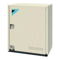
Provides visual representations of various indoor unit types and their external features.
Details the capacity range of indoor and outdoor units and their interconnections.
Presents detailed technical specifications for various outdoor unit models, including cooling/heating capacities.
Details technical specifications for different indoor unit types, covering capacity, dimensions, and sound levels.
Lists electrical and functional components for outdoor units, including symbols, models, and remarks.
Illustrates the refrigerant flow and components within the outdoor unit system for RXYSQ4/5/6P.
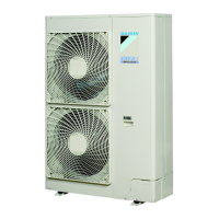
Provides a bird's-eye view of the outdoor unit, identifying key components and their locations.
Outlines the steps for conducting initial test operations after installation, including power supply checks.
Illustrates the layout of the outdoor unit's PC board, identifying indicators, switches, and connectors.
Details how to configure indoor unit settings using wired and wireless remote controls for installation.
Provides a table correlating system symptoms with potential causes and countermeasures for basic issues.
Explains how to use remote control functions like inspection, self-diagnosis, and service modes for troubleshooting.
Lists common malfunction codes displayed on the remote control and their corresponding troubleshooting steps.
Shows refrigerant piping diagrams for outdoor and indoor units, illustrating connections and components.
Provides detailed wiring diagrams for outdoor and indoor units, essential for installation and maintenance.
Lists available optional accessories for controllers and building management systems, detailing their models and functions.
Illustrates connection examples for piping, including refnet joints and pipe size selection criteria.
Provides tables showing thermistor resistance values at different temperatures for diagnostic purposes.
Details the relationship between pressure and output voltage for high and low-pressure sensors.
Explains the procedure for checking and replacing power semiconductors on the inverter PC board.
Describes the characteristics, pressure, and composition of R-410A refrigerant compared to older types.
Outlines safety laws, regulations, and proper handling/storage procedures for R-410A refrigerant cylinders.
Lists essential tools compatible with R-410A, highlighting differences from R-22/R-407C tools.
Provides step-by-step instructions for disassembling the outdoor unit for specific RXYSQ models.
Details the process for safely removing the top, front, and side panels of the outdoor unit.
Explains the procedure for removing the propeller fan and fan motor, including necessary precautions.
Outlines the steps for safely removing the compressor, including lead wire and terminal disconnection.