L
N
To the power supply
To unit B
Power cord
To unit A
connecting
cable
L
L
connecting
cable
Handle
Handle
Front
side plate
L
N
To the power supply
To unit B
Power cord
To unit A
connecting
cable
L
L
connecting
cable
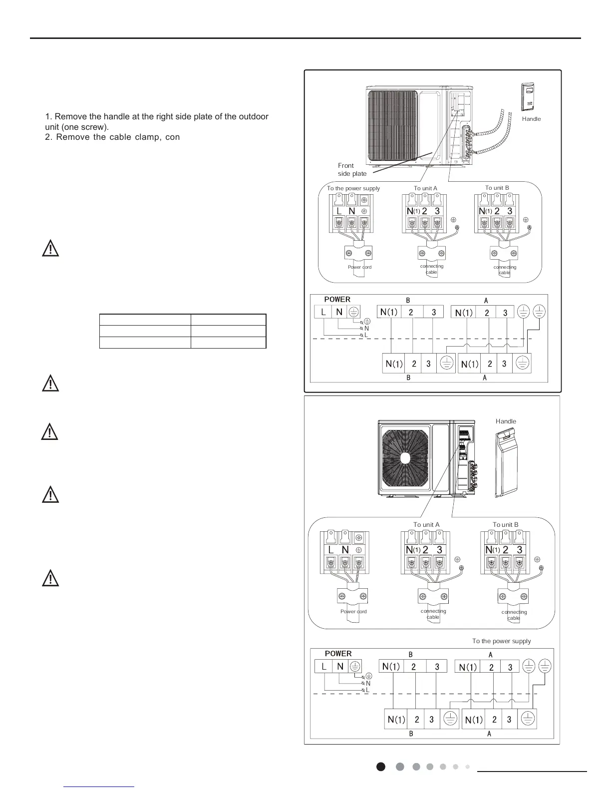
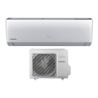
1. Remove the handle at the right side plate of the outdoor
unit (one screw).
2. Remove the cable clamp, connect the power connection
cable with the terminal at the row of connection and fix the
FRQQHFWLRQ7KH ¿WWLQJOLQHGLVWULEXWLQJPXVWEHFRQVLVWHQWZLWK
the indoor unit. terminal of line bank. Wiring should meet that of
indoor unit.
3. Fix power connection wire by wire clamp.
(QVXUHZLUHKDVEHHQ¿[HGZHOO
5. Install the handle.
Including an air switch with suitable capacity,please note
the following table. Air switch should be included magnet
buckle and heating buckle function, it can protect the
circuit-short and overload. (Caution: please do not use the
fuse only for protect the circuit)
Wrong wire connection may cause malfunction of
VRPHHOHFWULFFRPSRQHQWV$IWHU¿[LQJFDEOHHQVXUH
WKDWOHDGVEHWZHHQFRQQHFWLRQWR¿[HGSRLQWKDYH
some space.
..
An all-pole disconnection switch having a contact
separation of at least 3mm in all pole should be connected
LQ¿[HGZLULQJ
The connection pipes and the connectiong wirings
of the unit A and unit B must be corresponding to
each other respective.
The appliance shall be installed in accordance with
national wiring regulations.
1RWHWKHDERYH¿JXUHVDUHRQO\LQWHQGHGWREHDVLPSOH
diagram of the appliance and may not correspond to the
appearance of the units that have been purchased.
.
.
Air-conditioner Air switch capacity
. 10A
. 10A