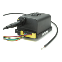
The Dakota Digital CRS-2000 & CRS-3000 Cruise Control System is a microprocessor-based unit designed for universal application in cars, light trucks, and vans. It offers enhanced adaptability and features for improved operation and easier installation.
Function Description:
The primary function of the Dakota Digital Cruise Control System is to maintain a set vehicle speed automatically. It achieves this by controlling the throttle based on speed signals from various sources. The system is designed to work with a range of engine configurations (3, 4, 5, 6, or 8 cylinders) and transmission types (manual or automatic).
Important Technical Specifications and Features:
Enhanced Adaptability:
- Cylinder Compatibility: Works with 3, 4, 5, 6, or 8-cylinder engines.
- Speed Signal Sources: Can utilize ECM, AC Generator, Magnets, or Pulse Sender as the speed signal source.
- Quiet Operation: Designed for quiet operation, allowing for more flexible mounting locations.
- Acceleration Rate: Selectable acceleration rates to suit user preference.
- Gain Control: Selectable gain control for fine-tuning performance.
- Transmission Compatibility: Compatible with both manual and automatic transmissions.
- Ignition System Compatibility: Works with Distributorless Ignition Systems.
Enhanced Features:
- Modular Design: Features a modular design for ease of integration.
- Wiring Harness: Includes a removable wiring harness with a locking device for secure connections.
- Water Sealing: Redesigned water sealing for improved durability and protection against environmental elements.
- Neutral Safety Switch (NSS) Compatible: Compatible with NSS for added safety, disengaging the cruise control if the transmission is accidentally shifted into neutral while in motion.
- Cruise Engaged Output: Provides a ground signal when the cruise control is engaged, which can be used to drive an external LED indicator.
- Self-Diagnostic: Equipped with a self-diagnostic procedure to assist in troubleshooting.
Easier Installation:
- No Vacuum Required: Eliminates the need for vacuum connections, simplifying installation.
- Smaller Module: Features a compact module design.
- Single Unit Mounting: Designed for single-unit mounting.
- Connectors: Utilizes connectors with positive contact and a locking mechanism for reliable connections.
- Clutch Switch: No clutch switch is needed for automatic transmissions (except for diesel applications).
- Throttle Hardware: Additional throttle hardware is included in the kit for various hook-up scenarios.
- Neutral Safety Connections: Compatible with neutral safety connections.
Improved Operation:
- Accurate Speed Control: Provides closer, more accurate control of the set speed.
- Coast/Reduce Speed: Accurate coast/reduce speed functionality.
- Tap-Up/Tap-Down: Allows for precise speed adjustments: 1 MPH per tap for tap-up and 1.5 to 5 KPH (2 to 3 MPH) for tap-down.
- Controlled Resume Rate: Features a controlled resume rate for smooth re-engagement.
Usage Features:
Control Switch Operations:
- ON: Activates the Cruise Control system. A green LED indicator will light up if equipped. A 3-second delay is required before setting speed.
- SET SPEED: Engages the system. Drive above 50 KPH (33 MPH), press and release SET/COAST, then remove your foot from the accelerator pedal. The vehicle will maintain the speed at release, within plus or minus 3 KPH (1-1/2 MPH).
- COAST: Press and hold SET/COAST to decrease speed. Releasing the button sets the new speed if above 50 KPH (33 MPH).
- ACCEL: Press and hold RESUME/ACCEL to increase speed. Releasing the button sets the new higher speed.
- TAP-UP: Quickly pressing and releasing RESUME/ACCEL gradually increases speed by 1.5 to 5 KPH (2 to 3 MPH) per tap.
- TAP-DOWN: Quickly pressing and releasing SET/COAST gradually decreases speed by 1.5 to 5 KPH (2 to 3 MPH) per tap.
- DISENGAGE: Depress the brake pedal slightly, or press the control switch to OFF. Depressing the brake pedal retains the set speed in memory, while turning OFF the switch erases it.
- RESUME: After disengaging, drive above 50 KPH (33 MPH), then press and release RESUME/ACCEL to return to the previously set speed.
Throttle Connection:
The manual provides detailed diagrams for connecting the servo to the throttle, covering basic OEM factory hook-ups and variations for aftermarket carburetors. Five types of throttle connections are described: Pulley Assembly Using The LOOP CABLE, Pulley Assembly Using T-BAR ADAPTOR, Pedal Attachment, Ford™ Throttle, and General Motors™ and Chrysler™ Throttle Using THREE BEAD CONNECTOR.
Anchoring Cruise Cable:
Three types of connectors are used to anchor the cruise cable: SNAP-IN ADAPTOR, General Motors™ Blank Anchor, and FLAG NUT. Instructions are provided for forming threads on the cable end and securing the adaptors.
Wiring Attachments:
- RED (Constant 12V): Connects to a fused terminal that feeds power to the brake lights.
- BROWN (Switched 12V): Connects to an accessory terminal of the fuse panel (10 amps), active in accessory and run positions.
- BLACK (Ground): Connects to a good chassis or firewall ground point.
- VIOLET (Cold Side of Brake Switch): Receives 12V only when the brake is depressed. LED brake lights require a relay for proper grounding.
- BLUE (TACH Source): Connects to the negative side of the ignition coil, or TACH terminal on GM HEI/MSD ignitions. This wire provides a safety feature to prevent engine over-rev.
- GRAY (VSS Source): Connects to the Vehicle Speed Sensor (VSS) wire or an auxiliary speed sensor.
- LIGHT GREEN (Optional Neutral Safety - NSS): Taped at the beginning of the harness, this wire provides an optional safety feature for automatic transmissions to disengage cruise if shifted into neutral.
- ORANGE (Optional Enable Output - ENO): Taped at the beginning of the harness, this wire supplies a ground to an external LED when the system is engaged.
Programming Switches:
The CRUISE MODULE has twelve (12) programming switches located under a rubber grommet. These switches must be set according to the vehicle's specifications for proper operation. Functions include Gain Sensitivity, VSS Pulses Per Mile, Engine Cylinder Setup Timer, Square/Sine Wave Input, Manual/Automatic Transmission, and Closed/Open Circuit Control Switch.
Maintenance Features:
Self-Diagnostic Testing Procedure:
The system includes a Red Self Diagnostic Surface Mount Light Emitting Diode (LED) to assist in troubleshooting. The procedure involves a series of steps to test the cruise control switch, brake switch connections, and VSS signal. This helps identify issues such as incorrect programming switch settings, faulty connections, or power problems.
Control Switch Testing Procedure:
Continuity charts are provided to test the control switch if it is suspected to be malfunctioning. This involves unplugging the 10-pin connector from the CRUISE MODULE and using a test light to verify voltage at specific wires under different switch positions.
TACH Signal Testing Procedure:
A dedicated procedure is available to test the TACH signal. This involves starting the engine with the ignition switch ON and observing the Diagnostic LED while revving the engine. A faster flashing LED indicates a valid TACH signal.
Troubleshooting Guide:
A comprehensive troubleshooting guide is included, listing common problems, possible causes, and solutions. This covers issues such as:
- Cannot Get Into Diagnostics: Violet wire not seeing ground, optional NSS wire grounded, poor black ground connection.
- Does Not Engage: LED tail-lights, violet wire not grounded through tail-light circuit, tach interference.
- Cruise Surges: Sensitivity set too high, VSS set incorrectly, tach interference.
- Engages Briefly, But Then Disengages: Too much slack in throttle cable, poor power on RED/BROWN wires, poor pulse generator ground, sensitivity set too high, tach interference.
Important Safety Procedures:
The manual emphasizes safety precautions, including disconnecting the negative battery cable before installation, avoiding specific mounting areas for the module, and ensuring proper throttle cable travel measurement to prevent damage or throttle hang-up. It also warns against modifying the product and stresses the importance of good judgment during installation. For vehicles with LED taillights, a relay (Dakota Digital RLY-1 or any 5-pin SPDT normally open relay) is required for proper cruise control operation.