EasyManua.ls Logo

Dakota Digital VHX-78C-MC User Manual

Dakota Digital VHX-78C-MC
42 pages
To Next Page IconTo Next Page
Page #1 background imageLoading...
Page #1 background image
650374
VHX-78C-MC
Dakota Digital VHX Instrument Installation for:
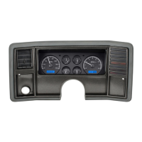
1978-‘88 Chevy Monte Carlo
1978-‘88 Chevy El Camino/GMC Caballero (will not fit clusters with sweep-style speedometer)
1978-‘83 Chevy Malibu (will not fit clusters with sweep-style speedometer)
Your new VHX-78C-MC kit includes:
Installation
Control Box
CAT5 Cable
Universal
Sender Pack
Installation Manuals
VHX Display
1. Remove the seven screws securing the bezel. Retain these screws.
1/8” Plastic Spacer

Questions and Answers:

Dakota Digital VHX-78C-MC Specifications

General IconGeneral
BrandDakota Digital
Product NameVHX-78C-MC
CategoryMeasuring Instruments
SeriesVHX
Display TypeDigital
Voltage12V
Fuel Level Sensor TypeOhm
Operating Temperature-40°F to 185°F

Summary

VHX-78C-MC Installation and Components

VHX-78C-MC Kit Contents

Lists all items included in the VHX-78C-MC kit.

Step 1: Bezel Removal

Instructions to remove bezel screws for installation.

Gauge Removal Steps

Steps 2 & 3: Removing Factory Gauges

Instructions for removing the blackout plate, lens, and factory gauges.

Housing Preparation and Display Mounting

Steps 4-6: Housing Modification and Display Mounting

Details on preparing the housing and mounting the new display.

Final Installation Assembly

Steps 7 & 8: Final Assembly

Completing the physical installation and reattaching the bezel.

VHX System Introduction

Important Odometer Preset Note

Reminder about the odometer preset option timing.

VHX Instrument System Features

Display Capabilities and Indicators

Overview of LCD displays, mileage, performance, indicators, and special outputs.

System Handling and Mounting

Care and Cleaning Guidelines

Guidelines for cleaning the VHX system components.

Control Box Mounting Instructions

Instructions and considerations for mounting the control box.

VHX System Wiring

Wiring Diagram Overview

Explains the wiring connections for the VHX system.

Control Box Terminal Descriptions

Status LED and Grounding

Explanation of the status LED and the importance of proper grounding.

Constant Power Connection

Details on connecting the constant power terminal.

Accessory Power and Tachometer Connections

Accessory Power (ACC. POWER)

Instructions for connecting the accessory power terminal.

Tachometer Signal Connection

Guidance on connecting the tachometer signal wire.

Speed Signal Connections

SPD + and SPD SND

Instructions for connecting the speed sensor positive and signal wires.

SPD -

Instructions for connecting the speed sensor ground wire.

Speed Output and Switch Inputs

Speed Output and Switch Terminals

Description of speed output and switch inputs (SW1, SW2).

Water and Oil Sensor Connections

Water Temperature Sensor (WTR SND)

Details on connecting the water temperature sender.

Oil Pressure Sensor (OIL SND)

Details on connecting the oil pressure sender.

Fuel Sensor and Auxiliary Connections

Fuel Level Sensor (FUEL SND)

Instructions for connecting the fuel level sender.

Auxiliary I/O and Display Cable

Notes on AUX I/O and display cable connections.

Indicator Input Connections

Cruise, Wait, Gear, 4x4, Turn Signals, High Beam

Describes connections for various indicator inputs.

Warning, Dimmer, and Other Connections

Brake, Check Engine, and Dim Connections

Instructions for connecting brake, check engine, and dimmer signals.

AUX I/O and Display Cable

Notes on AUX I/O and display cable connections.

Control Box Setup Menus Overview

Speed and Tachometer Setup

Overview of the SPEED and TACH setup options.

Volt, Water, Oil, and Fuel Setup

Overview of VOLT, WATER, OIL, and FUEL setup options.

Speedometer Setup and Calibration

Speed Sensor Setup

How to select the speed sensor input type.

Speedometer Calibration Methods

Auto Cal Procedure

Step-by-step guide for automatic speedometer calibration.

Adjust Mode Calibration

Method for calibrating the speedometer manually.

Speedometer Setup Options

Service Countdown and Speed Output

Setup for service reminders and speed signal output.

Tachometer Setup Options

Engine Cylinder and Update Rate

Configuring engine cylinders and display update rate.

RPM Warning and Signal Setup

Setting RPM warning points and tach signal type.

Volt and Water Temperature Setup

Volt Warning Setup

Configuring low voltage warnings.

Water Temp Sensor Setup

Selecting units and sensor type for water temperature.

Water Temperature Setup Options

Temp Warning and Test Modes

Setting temperature warnings and using the test mode.

Oil Pressure Setup

Oil Pressure Warning and Test

Configuring oil pressure warnings and using the test mode.

Fuel Sender Setup

Fuel Sender Type Selection

Choosing from pre-programmed or custom fuel sender types.

Fuel Sender Calibration and Testing

Custom Fuel Sender Curve Setup

Calibrating a custom fuel sender.

Fuel Sensor Test and Exit

Testing the fuel sensor and exiting setup.

Lighting Setup

Night and Day Brightness Adjustment

Setting backlight levels for different driving conditions.

Display and Indicator Configuration

Secondary Indicator Setup

Configuring indicator display locations.

Display Message Location

Selecting which LCD displays show readings.

Information and Odometer Setup

Information Menu (Software Version)

Accessing system information like software version.

Odometer Preset Menu

Setting the odometer to match the vehicle's current mileage.

LCD Message Contrast Adjustment

Normal Operation and Message Displays

Speed/LCD1 Message Displays

List of messages for the speedometer display.

Tach/LCD2 Message Displays

List of messages for the tachometer display.

Troubleshooting Guide: Power and Status

Power and LED Issues

Solutions for systems not turning on or LED status problems.

Troubleshooting: Speed and Tachometer Readings

Speedometer and Tachometer Issues

Solutions for incorrect or missing speed/tach readings.

Troubleshooting: Gauge and Indicator Functionality

Gauge and Indicator Problems

Solutions for fuel, oil, water, gear, and indicator problems.

VHX Series Specifications

Supply, Inputs, and Outputs

Technical specifications for power, inputs, and outputs.

Service and Warranty Information

Service and Repair Procedures

Guidelines for returning units for service or repair.

Dakota Digital Limited Lifetime Warranty

Details of the product warranty.

Related product manuals