EasyManua.ls Logo

Dakota Digital VHX User Manual

Dakota Digital VHX
34 pages
To Next Page IconTo Next Page
Page #1 background imageLoading...
Page #1 background image
MAN 650314C
1
VHX
Analog / Digital Gauge System
INSTALLATION AND OPERATION MANUAL
Please read this before beginning installation or wiring.
IMPORTANT NOTE!
This
system
has an odometer preset option that is only
available for the first 100 miles of operation. See odometer preset section (pg 26)
for in
structions
.

Table of Contents

Question and Answer IconNeed help?

Do you have a question about the Dakota Digital VHX and is the answer not in the manual?

Dakota Digital VHX Specifications

General IconGeneral
Display TypeLCD
Fuel GaugeYes
Water TemperatureYes
Oil PressureYes
OdometerYes
Trip MeterYes
ClockYes
SeriesVHX
Bezel MaterialAluminum

Summary

VHX System Introduction and Operation

Important Odometer Preset Note

Highlights the limited 100-mile window for setting the odometer.

VHX System Features Overview

Digital Display and Mileage Features

Details LCD display capabilities, mileage, trip, and service readings.

Performance, Indicators, and Special Outputs

Covers performance metrics, indicators, and special outputs like demo mode.

VHX Display Layout Examples

Visual Configurations of Gauges

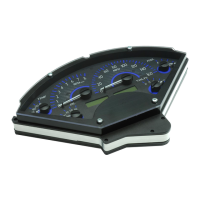
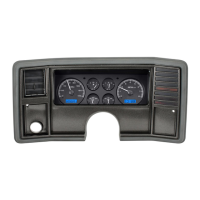
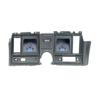
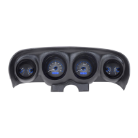
Illustrates various gauge and message center layouts for the VHX system.

Important System Handling and Mounting

Care, Cleaning, and Control Box Mounting

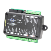
Guidelines for cleaning the system and safely mounting the control box.

VHX System Wiring Guide

Control Box and Sensor Connections

Overview of control box terminals and their connections to vehicle systems.

Control Box Terminal Descriptions: Power, Ground, and Status

Power, Ground, Status LED, and Basic Terminals

Details on constant power, ground, status LED, and initial terminal descriptions.

Control Box Terminal Functions: Inputs and Outputs

Accessory Power, Tachometer, and Warning Outputs

Describes ACC. POWER, TACH input, and WARN output terminal functions.

Speed Signal Wiring and Calibration

SPD Terminals for Speed Signal Input/Output

Explains wiring for speed sensor input and output signals.

Control Box Terminals: Switches and Adjustments

SW1, SW2, ADJ, and SPD OUT Terminals

Details on SW1, SW2, ADJ SND, ADJ -, and SPD OUT terminals.

Sensor Connections: Water and Oil

Water Temp and Oil Pressure Sensor Wiring

Describes connections for water temperature and oil pressure sensors.

Fuel Sensor and Indicator Connections

Fuel Level Sensor and Cruise Indicator Wiring

Details wiring for fuel level sender and cruise control indicator.

Vehicle Indicator and Input Connections

WAIT, GEAR, 4x4, Turn Signals, High Beam, Brake Inputs

Explains connections for various vehicle indicators and inputs.

System Indicators and Connectivity

Check Engine, Dimming, AUX I/O, Display Cable

Covers check engine indicator, dimming, BIM, and display cable connections.

Control Box Setup Menu Structure

Overview of Main Setup Categories

Lists the primary categories available in the control box setup menu.

System Setup and Calibration Procedures

Info, Odometer Preset, and Speedometer Calibration

Guides for accessing info, setting odometer, and calibrating the speedometer.

Speedometer Calibration Methods

Auto Cal and Adjust Calibration Techniques

Detailed steps for calibrating the speedometer using Auto Cal or Adjust modes.

Setup Options: Service, Speed Output, and Tachometer

Service Reminders and Speed Output Configuration

Covers service reminders, speed output settings, and tachometer setup options.

Tachometer Setup Details

Engine Cylinders, Update Rate, and Tach Signal

Configuration for engine cylinders, display update rate, and tach signal type.

Volt and Water Temperature Setup

Voltage Warning and Water Temp Settings

Adjusting voltage warning points and water temperature units/warnings.

Water Temperature Sensor Testing and Warnings

Water Temp Warnings and Sensor Test

Setting water temp warnings and testing the sensor's resistance.

Oil Pressure Setup and Testing

Oil Pressure Warnings and Sensor Test

Configuring oil pressure warnings and testing the oil pressure sensor.

Fuel Level Sensor Configuration

Selecting Fuel Sender Type and Custom Setup

Choosing the correct fuel level sender type and calibrating custom sensors.

Advanced Fuel Setup and Lighting

Custom Fuel Curve and Lighting Settings

Customizing fuel sender curves and adjusting display lighting brightness.

Display and Module Setup Options

Bus Interface Module and Display Configuration

Setting up BIM modules and configuring display message locations.

Display Configuration: Indicators and Location

Indicator Display and Message Location Settings

Customizing indicator visibility and message display locations.

System Information and Odometer Presets

Info Menu, Odometer Preset, and Speed Calibration

Viewing software info, PPM values, and presetting odometer miles.

Operation and Display Adjustments

LCD Contrast Adjustment and Normal Operation

Adjusting LCD contrast and understanding normal system operation.

Message Displays and Clock Functionality

LCD Messages and Clock Time Setting

Details on available messages and how to set the system clock time.

Troubleshooting Guide: Power and Tachometer Issues

System Power and Tachometer Reading Problems

Solutions for power-related issues and no tachometer readings.

Troubleshooting: Gauge and Sensor Accuracy

Tachometer, Speedometer, and Sensor Accuracy Issues

Addresses incorrect tach/speed readings and sensor error messages.

Troubleshooting: Gauge and Indicator Functionality

Fuel Gauge, Indicators, and Grounding Issues

Solutions for fuel gauge, gear shift, and indicator problems, including grounding.

Troubleshooting Specific Issues and Specifications

Indicator, Switch, Clock, and Specification Details

Troubleshooting specific indicators/switches and system electrical specifications.

Service, Repair, and Warranty Information

Product Service, Repair, and Limited Lifetime Warranty

Information on obtaining service, repair procedures, and warranty terms.

Related product manuals