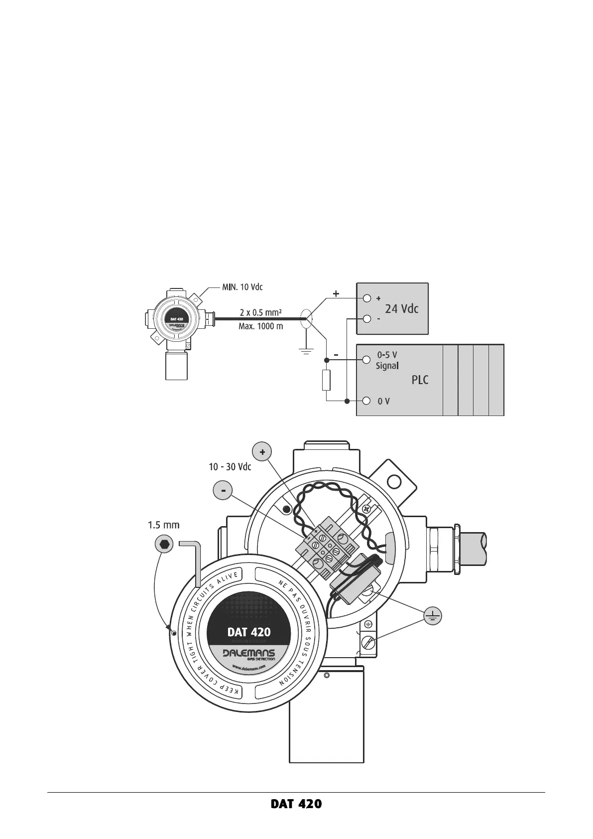
Connection to a PLC
To connect the DAT 420 gas detector to a PLC:
▪ Loosen the locking screw of the junction box cover using the 1.5 mm hex key and completely
turn the cover counterclockwise to unscrew it.
▪ Loosen the cable gland cap nut, insert the cable into the cable gland and tighten.
▪ Connect the wires to the 2-position terminal block according to the diagram below.
▪ The cable wires must be stripped and plugged so that the gap between the wire insulation
and the metal edge of the terminal connection does not exceed 1 mm distance.
▪ Equipotential bonding may be provided using either the internal or the external connection.
For the external connection, the bonding conductor should be at least 4 mm².
▪ Screw the cover back onto the junction box and hand tighten ¼ turn.
▪ Put the locking screw of the cover back in place and tighten with the 1.5 mm hex key.
▪ The cable shielding or screening must be grounded at the PLC.
▪ Connect a shunt resistor across the PLC input. Choose the resistor value according to the
PLC input scale (see above). The resistor must have a power rating of at least 1 Watt.
Figure 9: connection to a PLC