For instructions about the electrical connection of the PLC, please refer to the
original equipment instruction manual.
Prior to connecting the DAT 420 to a PLC please follow these instructions:
▪ Use an external stabilized power supply for the detector (+24 Vdc).
▪ Ensure that the polarity of the detector output signal matches the polarity of the PLC input.
▪ Please read the instructions below regarding the loop resistance.
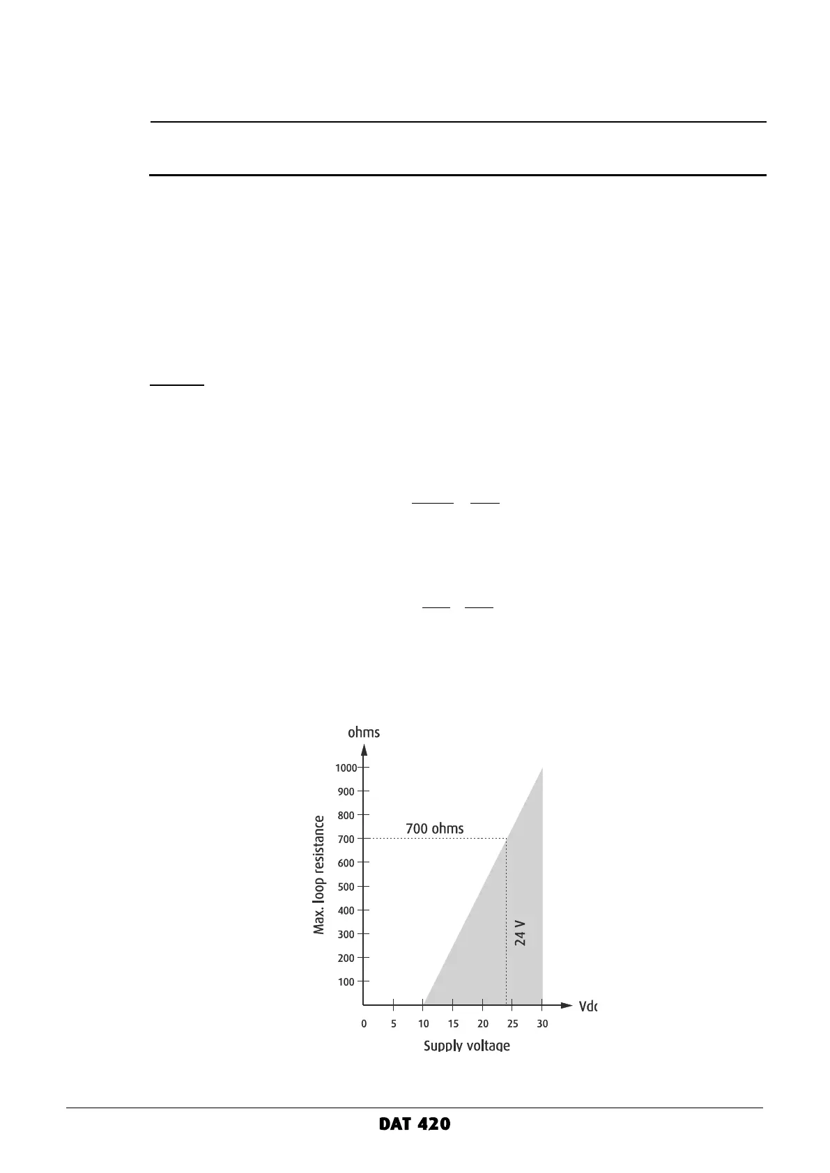
Loop resistance
The supply voltage applied to the detector has direct influence on the MAXIMUM loop resistance.
This resistance includes the cable resistance and the shunt resistor of the PLC.
Example
- The minimum operating voltage of the DAT 420 is 10 Vdc.
- Consider a supply voltage of 24 Vdc, the allowable voltage drop due to the loop resistance is
14 Vdc.
- The MAXIMUM loop resistance will be: