Dametric AB BRM-DM1/2 Installation manual
BRM-DM12 IM EN.docx October 14, 2019 Page 3 of 6
5 Installation
5.1 General
This manual shows all connections to the module. Some of the functions are however not activated in the
BRM-DM1 variant.
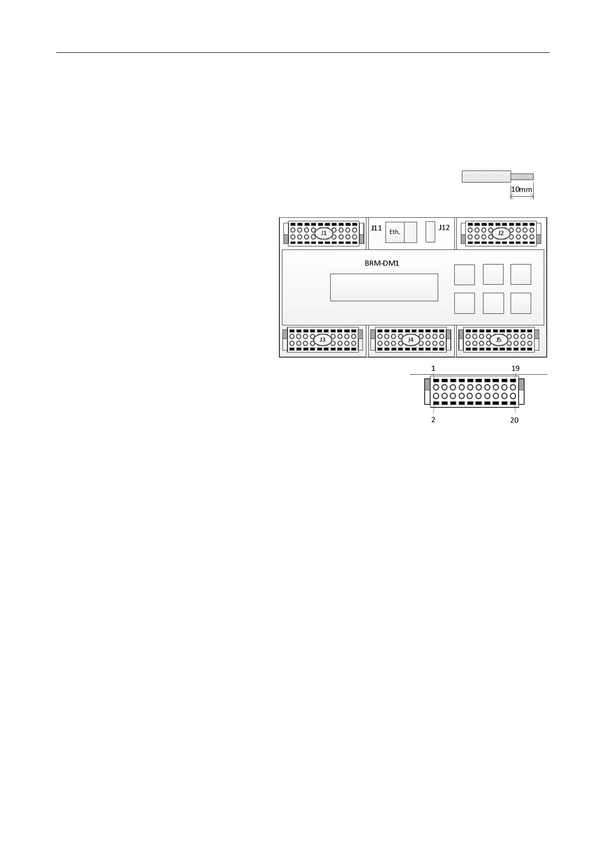
All connections are done to 20-pole connectors with spring loaded sockets.
Maximum allowed conduit area is 1.5mm
2
or AWG 16. Do not use clamping sleeves.
The strip length should be 10mm (0.40 inch). A too short a length might make the cable
loose, at too long, the result will be a piece of non-isolated cable.
The cable shields should be joined with a 1.0 mm2 isolated cable and then mounted to the
connector.
5.2 Connector placing
5.3 Connector J1, +24VDC, CAN-1
1,2 +24VDC Power supply to the module
3,4 0VDC Power ground
5,6 CAN1-H CAN1-interface H-signal (use twisted pair cable for
CAN1-H and CAN1-L)
7,8 CAN1-L CAN1-interface L-signal
9,10 CAN1-R CAN1-interface termination pole (jumper between 9 and 10 for 120 termination)
11,12 0VDC Signal ground
13 DI 1 Digital input 1
14 DI 2 Digital input 2
15 DI 3 Digital input 3
16 DI 4 Digital input 4
17 DI 5 Digital input 5
18 DI 6 Digital input 6
19 DI 7 Digital input 7
20 DI 8 Digital input 8
5.3.1 Inputs for the SSM function option
Use DI7 and DI8 as inputs for the Safeset supervision option.
J1/19 DI7 Connect to pulse sensor for the motor side.
J1/20 DI8 Connect to pulse sensor for the refiner side.
USB
 Loading...