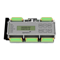
Dametric AB BRM-DM1/2 Installation manual
BRM-DM12 IM EN.docx October 14, 2019 Page 4 of 6
5.4 Connector J2, AGS/CPM interface (option)
1,2 +24VDCin Power supply input for AGS/CPM
3,4 0VDC Power ground
5,6 +24VDCout Power supply output to AGS/CPM
7,8 0VDC Power ground
9,10 CAN2-H CAN2-interface H-signal (use twisted pair cable for
CAN2-H and CAN2-L)
11,12 CAN2-L CAN2-interface L-signal
13,14 CAN2-R CAN2-interface termination pole (jumper between 13 and 14 for 120 termination)
15,16 CAN2-C CAN2-interface common (for cable shielding)
17,18 0VDC Signal ground
19,20 0VDC Signal ground
Connect K-AGP25 according to the figure. Cut away excessive
wires.
GY=grey, BU = blue, PK = pink, RD = red, SH = shield.
Connect K-AGP25 according to the figure.
(WH/BU = white / blue, BU/WH = blue /white, SH = shield
A jumper between 13 and 14 terminates the bus with 120 .
5.5 Connector J3, CMD, Digital outputs
1,2 +24VDCin The power supply input for the CMD system
3,4 0VDC The power ground
6,8,10,12 0VDC The power ground
5 SM-WA1 To control motor winding
7 SM-WA2 To control motor winding
9 SM-WB1 To control motor winding
11 SM-WB2 To control motor winding
13 DO1 Digital output 1
14 DO2 Digital output 2
15 DIO3 Digital output 3
16 DIO4 Digital output 4
17 DIO5 Digital output 5
18 DIO6 Digital output 6
19 DI7 Digital output 7
20 DI8 Digital output 8
1
2
19
20
BRM‐DM1
A+
A‐
B+
B‐
GND
J3/5
J3/7
J3/9
J3/11
J3/12
CM‐2NM...
Step
motor
A+
A‐
B+
B‐
GND
1
2
3
4
GND
K‐CM25K
BRM‐DM1
GY(+24V)
BU(+24V)
PK(0V)
RD(0V)
SH
J2/5
J2/6
J2/7
J2/8
J2/17
K‐AGP25
BRM‐DM1
WH/BU
BU/WH
SH
J2/9
J2/11
J2/15
J2/13
J2/14
K‐CAN1P25
 Loading...