Dametric AB BRM-DM1/2 Installation manual
BRM-DM12 IM EN.docx October 14, 2019 Page 5 of 6
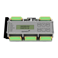
5.6 Connector J4, POM, VIM, TVD
1 POM-T1 K-POT25/white (to POT-50 transducer)
2 POM-T2 K-POT25/brown
3 POM-T3 K-POT25/green
4 POM-T4 K-POT25/yellow
5 POM-T5 K-POT25/grey
6 POM-T6 K-POT25/rose
7 0VDC K-POT25/shield
8 0VDC Signal ground
9 VIM-EP K-VIMS25/white (to VIM-T2 transducer)
10 VIM-SP K-VIMS25/brown
11 VIM-SN K-VIMS25/green
12 VIM-EN K-VIMS25/yellow
13 0VDC K-VIMS25/shield
14 0VDC Signal ground
15 TVD-EP K-TVDS25/white (to TVD-T2 transducer)
16 TVD-SP K-TVDS25/brown
17 TVD-SN K-TVDS25/green
18 TVD-EN K-TVDS25/yellow
19 0VDC K-TVDS25/shield
20 0VDC Signal ground
5.7 Connector J5, HPM, OTM, AIN
HPM-A and HPM-B measures two pressure transmitters.
1 HPM-SAP HPM-A, Analog input, positive, 4-20mA
2 HPM-SAN HPM-A, Analog input, negative, 4-20mA
3 HPM-SBP HPM-B, Analog input, positive, 4-20mA
4 HPM-SBN HPM-B, Analog input, negative, 4-20mA
5,6 0VDC Signal ground
OTM-1 and OTM-2 measures PT100 sensors in a 3-wire connection.
The compensating and negative wires are internally connected in the transducer end.
7 OTM-E1 OTM-1, Excitation, PT-100
8 OTM-S1 OTM-1, Compensation, PT-100
9 OTM-N1 OTM-1, Negative, PT-100
10 0VDC Signal ground
11 OTM-E2 OTM-2, Excitation, PT-100
12 OTM-S2 OTM-2, Compensation, PT-100
13 OTM-N2 OTM-2, Negative, PT-100
14 0VDC Signal ground
15,16 0VDC Signal ground
MPM and AIN measures active 4-20mA input signals, that is – the electrical current loop is not
powered from the BRM unit.
17 MPM-IP MPM analog input, positive (4-20mA)
18 MPM-IN MPM analog input, negative (4-20mA)
19 AIN-P Analog input, positive (4-20mA)
20 AIN-N Analog input, negative (4-20mA)
5.8 Connector J11, Ethernet
RJ45 connector for the Ethernet cable.
Connect the cable to the switch of the local GMS network.
5.9 Connector J12, USB
USB-A connector for a memory stick.
1
2
19
20
1
2
19
20
 Loading...