The Dametric BRM-DM1 and BRM-DM2 are GMS Basic Refiner Modules designed for industrial applications, likely in the pulp and paper industry, given the context of "refiner" and "rotor." These modules serve as a user interface and control system for managing various parameters related to refiner operation, including rotor position, vibration, temperature, motor power, and gap control.
Function Description:
The core function of the BRM-DM1/2 is to monitor and control the operational aspects of a refiner. This involves:
- Rotor Position Control: The module manages the position of the refiner rotor, which is crucial for controlling the refining gap and process. Parameters like "POM Direction," "POM Ratio," "POM Zero calibr.," and "POM Span calibr." are used for precise calibration and control of the rotor's movement. The "POM Work mode" allows for different operational modes.
- Vibration Monitoring: The device monitors both "Ref. vibration" (VIM) and "Touch vibration" (TVD). This is critical for detecting imbalances, wear, or other mechanical issues that could affect refiner performance and safety. Alarm limits (e.g., "VIM Al.Lim. 1HH," "TVD Al.lim.1 Hg2") can be set to alert operators to excessive vibration. The "TVD Pro.adj.sen." allows for adjusting sensitivity during production.
- Temperature Monitoring: The module tracks temperatures "fr. Bearing" (OT1) and "to Bearing" (OT2), which are essential for preventing overheating and ensuring the longevity of the refiner's bearings. Alarm limits (e.g., "OT1 Al.lim. 1HH") can be configured.
- Main Motor Power Control: The "Main motor power" (MPM) function monitors the power consumption of the refiner's main motor. This helps in optimizing energy usage and detecting potential overloads or underloads. Alarm limits (e.g., "MPM Al.lim. 1LL") and filtering options are available.
- Hydraulic Pressure Monitoring: The module monitors hydraulic pressure for control purposes, with separate channels for "Hydr.pressure. A" (HPA) and "Hydr.pressure. B" (HPB). This is vital for systems that use hydraulics to adjust the refiner gap or other components. Alarm limits and calibration parameters are provided.
- Control Motor Management: The "Control motor" (CMD) function manages the motor responsible for adjusting the refiner's components, such as the screw pitch. It includes parameters for speed, direction, and current consumption.
- FeedGuard Function: The "FeedGuard func." (FG) is a safety feature designed to protect the refiner. It monitors rotor travel distance, piston delay, and other parameters to prevent damage, possibly from foreign objects or process upsets.
- Rotor Move Control (BRM-DM1 only): The "Rotor Move Ctrl." (RMC) function on the BRM-DM1 allows for dynamic adjustment of the production position based on motor power and time limits. It supports "Static op." (production position not changed) and "Dynamic op." (production position decreased automatically).
- Rotor Move Adjustment (BRM-DM1 only): The "Rotor Move Adj." (RMA) function on the BRM-DM1 facilitates calibration and wear measurement. It offers "Static," "Manual," "Automatic," and "PLC ctrl." modes for touch point detection and wear compensation.
- Gap Control Rotor (BRM-DM2 only): The "Gap Control Rot." (GCR) function on the BRM-DM2 is specifically for gap control, with different "Work mode" options for Valmet single disc and CD-refiners. It includes parameters for interval, deadband, gain, filter, and alarm limits for over and under gap conditions, as well as control speed.
- Gap Control Stator (BRM-DM2 only): The "Gap Control Sta." (GCS) function on the BRM-DM2 mirrors the rotor gap control but applies to the stator in a CD-refiner.
- Gap Guard (BRM-DM2 only): The "Gap Guard" (GGD) function on the BRM-DM2 sets allowed gap values and gain for both rotor and stator to prevent damage.
- Digital In/Out: The "Digital in/out" (DIO) function allows for configuring and monitoring digital inputs and outputs, providing status indications in hexadecimal format.
- AGS Interface (BRM-DM2 only): The "AGS Interface" function on the BRM-DM2 supports different gap sensors, including TDC-sensor and AGS-sensor.
- Safeset Monitor (BRM-DM2 only): The "Safeset Monitor" (SSM) on the BRM-DM2 tracks fault pulses, rotor speed, and measure indexes per turn, likely for safety and operational integrity.
- Analog Out Module: The "Analog Out Mod." (AOM) allows for setting measure functions for multiple channels on AOM-modules, enabling the output of various process values.
- CAN-Eth.-Conv. (BRM-DM2 only): The "CAN-Eth.-Conv." (CEC) function on the BRM-DM2 handles the communication interface, including IP address and mask, and connectivity to the sum alarm function.
Important Technical Specifications:
While specific numerical values for ranges, limits, and accuracies are not provided in the general description, the manual outlines the types of parameters that can be configured. These include:
- Alarm Limits: Multiple alarm limits (e.g., 1HH, 2H, 3L, 1LL) for high-high, high, low, and low-low conditions across various measurements (vibration, temperature, pressure, motor power).
- Calibration Parameters: Zero and span calibration for rotor position, hydraulic pressure, temperature, and motor power, ensuring accurate measurements.
- Ranges: Configurable ranges for hydraulic pressure and main motor power.
- Filter Times: Filter times for main motor power and gap control, to smooth out measurements and prevent spurious alarms.
- Speeds: Rotor travel speeds (low and high) for the control motor, and rotor movement speed for gap control.
- Communication: Support for industrial bus types (Profinet, Profibus, Ethernet IP) and CAN node numbers. The BRM-DM2 specifically includes CAN-Ethernet conversion.
- Hardware Revision: The unit tracks its actual hardware revision.
- DCS Clock: Synchronizes with a DCS/PLC system via the industrial bus.
Usage Features:
The BRM-DM1/2 offers a user-friendly interface for configuration and monitoring:
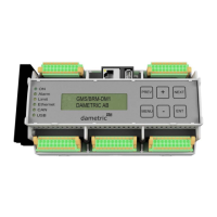
- Built-in Display and Buttons: The unit features a built-in display and buttons (MENU, PREV, NEXT, PLUS, MINUS, ENT) for direct interaction. This allows operators to select functions, scroll through parameters, adjust values, and save settings.
- MENU (short): Returns to the base level of the chosen function.
- MENU (>1s): Returns to the basic display indication.
- NEXT/PREV: Steps between functions or digits during edit.
- PLUS/MINUS: Selects parameters or increases/decreases digit values.
- ENT (short): Toggles between select and edit modes.
- ENT (>1s): Saves the parameter to EEPROM.
- Panel-PC Integration: For more detailed information and easier configuration, the module can be connected to an external GMS Panel-PC. This provides a richer user experience with descriptions of parameters during editing.
- LED Indicators: A set of LED indicators (ON, Alarm, Limit, Ethernet, CAN, USB) provides quick visual feedback on the unit's status, including power supply, alarm conditions, and network activity.
- Parameter Documentation: Users are advised to maintain a parameter list to document settings, which is crucial for module replacement or troubleshooting.
Maintenance Features:
The manual implicitly suggests several maintenance-related features:
- Calibration: Regular zero and span calibration procedures are essential for maintaining the accuracy of various sensors (rotor position, hydraulic pressure, temperature, motor power). The manual refers to a "calibration manual" for detailed instructions.
- Alarm System: The comprehensive alarm system, with multiple alarm limits for different parameters, helps in proactive maintenance by alerting operators to potential issues before they escalate. The "Off/On/On+Al" setting allows for connecting parameters to a sum alarm function.
- Wear Measurement: The "RMA Wear setting" and "RMA Wear offset" on the BRM-DM1 are specifically designed for measuring plate wear, which is a critical maintenance aspect in refiners.
- Status Monitoring: Various status indicators, such as "RMA Status" and "DIO Out Status," provide insights into the operational health of the module and connected components.
- Firmware Updates: The "BRM HW. Rev.no." and "BRM DCS clock" parameters suggest that the device's firmware and synchronization can be managed, which is important for updates and compatibility.
- Troubleshooting: The detailed parameter descriptions and menu structures aid in diagnosing issues by allowing operators to inspect current settings and measured values. The "BRM Test func." is also available, though noted as "not used" in the provided text.