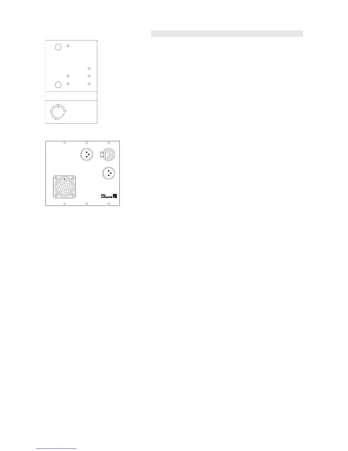
Fig. 5: B2-SUB controller rear panel
One B2-SUB cabinet can be driven by a single A1 mainframe fitted with
a B2-SUB controller module.
In standard mode the A1/B2 system is dedicated for the use with d&b
F2 systems.
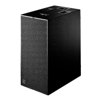
INFRA
The INFRA setting is available. The characteristics of the INFRA setting
are explained in the previous section "Operation with D12 - Controller
settings".
Controller module rear panel
A single 8 pin CACOM output socket is fitted to the module rear panel.
An additional balanced XLR output marked C4-OUT is also provided on
the module rear panel. The C4-OUT signal can be used to drive C4-
SUB controller inputs when a B2 is used as an infrabass system for C4-
SUBs. In case of a power or mainframe failure, a bypass relay in the B2
controller module connects the pins of the C4-OUT socket directly to
those of the module INPUT socket allowing the continued operation of
the C4-SUB and TOP cabinets.
B2-SUB Manual (3.2 EN) Page 6 of 8
 Loading...