MAINTENANCE & REQUIREMENTS:
• Never use more than two "MINI-MULTI ADJUST"
hinges on any gate.
• Ensure the gate does not swing beyond 180˚.
• Each hinge must have equal tension at all times.
• Remove all other types of hinges and self-closing devices.
• Do not lubricate with oil based lubricants.
• Never remove "MINI-MULTI ADJUST" hinges from gate
until spring tension is released.
• Never disassemble or physically alter these hinges
•inst-tcama_14/12/11
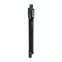
TCAMA000000PA
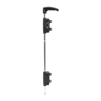
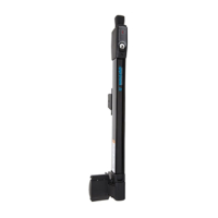
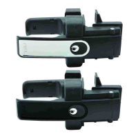
Example of right-hand hinged gate
FITS BOTH RIGHT-HAND OR
LEFT-HAND HINGED GATES
Congratulations on your purchase of D&D Technologies’ Tru-Close "Mini-Multi Adjust" Hinge. We are condent
this product will provide you with a lifetime of reliable gate closure (see limited Lifetime Warranty below).
Enclosed in this package is a tension adjustment sticker that you can place on your gate or keep in a drawer for
future reference.
Tools required: Electric or cordless drill (use low clutch settings) with #2 Phillips-head driver, Phillips-head #2
hand screwdriver, large slot-head hand screwdriver,
5
/32” (4mm) drill bit, straight edge level, pencil & a
7
/16” (11mm) wrench.
Some important points regarding the installation of the "Mini-Multi Adjust" Hinges:
• These hinges are designed to be tted to gates weighing no more than 55 lb (25kg). This is based upon a 5’Hx3’W gate (1524x915mm).
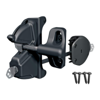
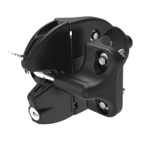
• The larger brackets B & D are always to be located on the fence post. When xing the hinges to a left-hand hinged gate, ensure that the bottom
hinge is mounted high enough from the ground to allow access to the tension adjustor from underneath.
• The hinges should be installed as far apart from each other as practicable, for optimum performance.
• Minimum gap between fence post and gate frame is
3
/4” (19mm).
• Maximum gap: TCAMA1: 1
1
/2” (38mm), TCAMA2: 2” (51mm) , TCAMA3: 1
1
/4” (32mm).
INSTALLATION PROCEDURE:
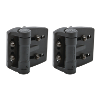
Step 1 – Installing the 4 MOUNTING BRACKETS
A. Determine the location of the gate in the mounted position. Prop the gate up with
bricks, wood or a suitable material to keep the gate level. On the fence post, mark the
top of the gate as shown at point ‘Z’.
B. From point ‘Z’, measure down the desired distance ‘X’ on the fence post for the
center of bracket B. For centering and leveling bracket A, align the center of both
brackets with centerlines as indicated by the dashed lines. Follow the same procedure
for brackets D and C. (Note: The top of the smaller brackets A and C should never be
installed closer than 1
3
/16” [30mm] from the top or bottom of the gate.)
C. Using the pencil, mark the center of all screw holes on all Mounting Brackets. Using
the self-drilling screws provided, x brackets A and C to the gate frame and then brack-
ets B and D to the fence post. (Note: Each bracket has four screw holes; two at the front
and two in the side xing leg. If you are xing the hinges to a metal gate or to a vinyl
gate with metal stiffeners, pre-drill using the
5
/32” [4mm] drill bit.)
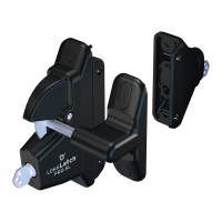
Step 2 – Installing the 2 HINGE BODIES
A. Slide the Hinge Bodies over the threaded studs in brackets A and C on the gate frame.
This is the side of the hinge with the VERTICAL slots. Make sure the threaded studs are in
the center of the vertical slots. Use the dome nuts supplied to secure the hinges. Finger
tighten only at this point.
B. Move the gate to the proper position to allow you to slide the HORIZONTAL slots over
the threaded studs in brackets B and D. With the remaining dome nuts, x them onto
the threaded studs. Finger tighten only at this point.
C. If required, loosen the dome nuts on brackets A and C and lift the gate up so that
the top is in alignment with the mark ‘Z’ you made earlier. Make sure the gate is level.
Re-tighten the dome nuts by hand.
D. To ensure the gate is horizontally positioned into the center of the gate opening,
loosen the dome nuts on brackets B and D. Find the center position for the gate and
then re-tighten the dome nuts by hand.
E. Step back and make sure the gate is in the proper position. If satised, rmly secure
all dome nuts by using the
7
/16” (11mm) wrench. DO NOT OVERTIGHTEN THE
DOME NUTS.
INSTALLATION INSTRUCTIONS
AUSTRALIA: Unit 6, 4-6 Aquatic Dr, Frenchs Forest NSW 2086
USA: 7731 Woodwind Drive, Huntington Beach, CA 92647
www.ddtechglobal.com
For a downloadable Adobe Acrobat (.PDF) version of our Limited LIFETIME WARRANTY,
go to our website at www.ddtechglobal.com