Do you have a question about the Danfoss 3 Series and is the answer not in the manual?
Specifies that assembly, installation, commissioning, and maintenance must be carried out by qualified personnel.
Alerts users to pay attention to the installation's permitted system pressure and operating temperature.
Warns users about hot surfaces that can cause burns.
Highlights the need to establish a way to shut off all energy sources and keep wires from hot pipes.
Instructions for removing packaging and disposing of materials according to local legislation.
States that assembly, installation, and commissioning must be performed by an authorized HVAC technician.
Guidance on how to lift the unit, specifying specific points for safe handling.
Recommends allowing sufficient space around the HIU for mounting and future maintenance.
Ensures the wall and fastenings can support the unit's gross weight.
Emphasizes re-tightening screw fittings after transit vibrations.
Details the process for removing the inspection and service hatches.
Describes the steps for removing the side frame of the unit.
States that all electrical installation work must be performed by an authorised electrician.
Outlines requirements for potential bonding according to relevant standards.
Specifies that electrically connected HIUs must be disconnected for repairs.
Details the steps for mounting energy meters, including closing valves and loosening nuts.
Notes that energy meter sensors are mounted in the sensor pockets.
Describes the process of filling the heat exchanger with water until it reaches working pressure.
Explains the function of the HTG pressure gauge and safety precautions.
Details the pre-pressure requirement for the HIU based on system head.
Instructs to start the pump and adjust it to its highest speed.
Guides on how to vent the installation after radiators have warmed up.
Advises adjusting the pump speed to recommended settings.
Explains the pump stop function requirement for underfloor heating applications.
Details temperature settings and relation between scale numbers and closing temperature.
Explains how flow temperature is controlled using the thermostatic controller.
Provides steps for removing the RAVK sensor from the valve.
Describes the 'first open' function and its disabling during commissioning.
Offers recommended settings for the circulator pump based on installation factors.
Details how to access the safety valve for inspection or maintenance.
Recommends regular cleaning of strainers as part of maintenance.
Suggests checking operating parameters and meter readings.
Advises checking supply and flow temperatures.
Recommends checking all connections for leaks.
Provides causes and solutions for incorrect flow temperature issues.
Addresses problems where the primary return temperature is excessively high.
Offers solutions for troubleshooting noise issues within the unit.
Guides on proper disposal of the product and its components according to local legislation.
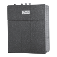
This document serves as an operating guide for the Termix VX-IV - 3 Series DS Fully insulated heat interface unit (HIU), designed for connecting to a heat network to provide space heating. It outlines the necessary procedures for assembly, installation, commissioning, daily operation, maintenance, and dismantling, emphasizing safety precautions throughout.
The Termix VX-IV - 3 Series DS is a heat interface unit (HIU) that connects to a heat network to provide space heating. It is designed to be installed in a frost-free location and integrates various components to manage the heating process. Key components include a heat exchanger, a circulator pump, thermostatic valves, a differential pressure controller, and an expansion tank.
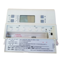
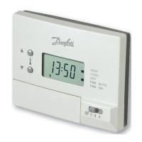
The unit's heating controls are managed by a RAVK controller, which allows for temperature setting within a range of 35-75 °C. This thermostatic control adjusts the flow temperature in the space heating circuit based on the selected setting, ensuring efficient and comfortable heating. The differential pressure controller smooths out pressure fluctuations from the heat network, maintaining a steady operating pressure within the HIU. The circulator pump, a Grundfos UPM3 AUTO, can operate in constant pressure, proportional pressure, or constant speed modes, adapting its performance to system requirements and reducing noise. An IMIT thermostat is also included, particularly for underfloor heating applications, to limit the flow temperature and shut off the pump and primary on/off valve if the temperature exceeds a preset limit (typically 60 °C). A safety valve is incorporated to protect the HIU from excessive pressure, with a blow-off pipe designed to discharge freely.
For energy measurement, the HIU is equipped with a fitting piece for an energy meter, and sensor pockets are provided for the energy meter's sensors. The unit also includes isolation valves, a filling/drain valve, and manual air vents for both the secondary and primary sides of the system.
Before installation, the existing system should be flushed. The unit is designed for wall mounting using keyholes on the backplate, with additional holes for flush mounting. Proper orientation is crucial for component and label visibility. All union connections must be checked and re-tightened after transport and again after filling the system with water and putting it into operation, due to potential vibrations.
Lifting the HIU should be done by the pipes fixed to the backplate or by the backplate itself, following specific lifting instructions provided in the guide. The inspection and service hatches, along with the side frame, can be temporarily removed for access during installation and maintenance.
Commissioning involves a series of checks: ensuring pipes are connected correctly, slowly opening isolation valves to fill the HIU with water, re-tightening all union fittings, venting the heating circuit, and monitoring the unit's operation for temperature, pressure, thermal expansion, and leaks. Once these steps are completed and the HIU functions according to design, it can be put into use.
Filling the primary heating system requires a flushing bypass and should only be done with heating network water after flushing. For the secondary heating system, the heat exchanger must be slowly filled until it reaches working pressure, observing the pressure gauge. The expansion vessel is supplied pre-pressurized, and the required pre-pressure depends on the system head.
Start-up involves starting the circulator pump at its highest speed for 10 minutes, then opening the primary isolation valves and observing the unit for proper operation and absence of leaks. The system should be vented after radiators warm up, and pump settings adjusted as recommended. Strainers on both primary and space heating circuits should be checked and cleaned regularly.
For underfloor heating, the circulation pump must be connected to the pump stop function of the underfloor heating controller. If all underfloor heating circuits are closed, the pump must be stopped to prevent seizure and warranty forfeiture; if this is not possible, flow must continue through a bypass.
The HIU requires minimal monitoring beyond routine checks. It is recommended to read the energy meter at regular intervals and record the readings. Regular inspections should include:
In case of malfunction, troubleshooting steps include verifying power supply, checking and cleaning the Heat Network pipe strainer, confirming normal Heat Network flow temperature, and ensuring sufficient differential pressure. After troubleshooting, all union connections should be tightened, any fluid spills cleaned, the HIU balanced if necessary, and pressure and temperature levels checked to ensure they are normal.
Spare parts can be ordered from SAV Systems Ltd., requiring the HIU's serial number found on the unit label.
Dismantling the unit requires ensuring all isolation valves are closed, the 230V plug is removed, and the unit has cooled down. The product consists of materials that should not be disposed of with household waste; components must be sorted into various groups for disposal according to local legislation. Suitable work gloves are recommended for handling and lifting the HIU during maintenance and dismantling.
| Power Supply | 230 V AC |
|---|---|
| Housing Material | Plastic |
| Connection Type | Screw terminals |
| Mounting | Wall mounted |
| Relative Humidity | non-condensing |