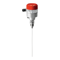
The Danfoss AKS 4100/4100U is a coaxial D14 version level sensor designed for measuring liquid levels in various refrigerants and non-corrosive gases/liquids. It is specifically intended for installation in a standpipe (column/bypass/stilling well), which is recommended for applications involving highly conductive foam, turbulent or agitated liquids, or when servicing the sensor.
Function Description:
The AKS 4100/4100U operates as a passive 2-wire, loop-powered 4-20 mA sensor. It measures the liquid level by detecting changes in dielectric constant along its probe length. The sensor outputs a 4-20 mA signal that corresponds to the measured liquid level, scaled according to user-defined parameters. The output can represent distance from a reference point, liquid level, or percentage/mA output of the measuring range. For CO2 applications, it is mandatory to input the dielectric constant. The device can be programmed with or without a Human Machine Interface (HMI) display.
Important Technical Specifications:
- Supply Voltage: 14-30 V d.c. (min/max) for a maximum output of 22 mA at the terminal.
- Load (RL):
- Default (Error output set to 3.6 mA): RL [Ω] ≤ ((Uext -14 V)/20 mA).
- (Error output set to 22 mA): RL [Ω] ≤ ((Uext -14 V)/22 mA).
- Cable Gland:
- AKS 4100: PG 13, M20x1.5 (cable diameter: 6-8 mm / 0.24-0.31 in.).
- AKS 4100U: 1/2 in. NPT.
- Terminals: Spring loaded, 0.5-1.5 mm² (~20-15 AWG).
- Enclosure: IP 67 (~NEMA type 4X).
- Refrigerant Temperature: -60°C to 100°C (-76°F to 212°F).
- Ambient Temperature: -40°C to 80°C (-40°F to 175°F). For HMI: -20°C to 60°C (-4°F to 140°F).
- Process Pressure: -1 barg to 100 barg (-14.5 psig to 1450 psig).
- Mechanical Process Connection: With 5 m (197 in.) Ø2 mm (0.08 in.) stainless cable.
- AKS 4100: G1 inch pipe thread (aluminium gasket included).
- AKS 4100U: 3/4 in. NPT.
- Available Probe Lengths:
- AKS 4100: 500 mm, 800 mm, 1000 mm, 1200 mm, 1500 mm, 1700 mm, 2200 mm.
- AKS 4100U: 19.2 in., 30 in., 45 in., 55 in., 65 in., 85 in.
- Qualified and Approved Refrigerants:
- R717/NH3: -40°C to 50°C (-40°F to 122°F).
- R744/CO2: -50°C to 15°C (-58°F to 59°F).
- R22: -50°C to 48°C (-58°F to 118°F).
- R404A, R410A: -50°C to 15°C (-58°F to 59°F).
- R134A: -40°C to 50°C (-40°F to 122°F).
- R507: -60°C to 15°C (-76°F to 59°F).
Usage Features:
- Assembly: The coaxial probe is segmented and requires assembly. The stainless steel wire must be carefully fed through the center hole of plastic spacers in each tube segment, ensuring it is not permanently creased or kinked. Segments are tightened using a 17 mm open-end wrench. The end connector is attached to the bottom of the assembled tube and secured with a 3 mm hex key. The stainless steel wire is then pulled taut with pliers and locked with two 3 mm hex key set screws. Excess wire is cut approximately 20 mm (0.8 in.) below the end connector.
- Mounting: The assembled probe, without the signal converter, is fitted into the standpipe. The mechanical process connection is tightened to 120 Nm (89 lb/ft) using a torque wrench. The signal converter is then slid onto the mechanical process connection and secured in the desired position with a 5 mm hex key.
- Electrical Connection: The device features output terminals for current output (positive and negative) and a grounding terminal. The terminal compartment cover is removed using a 2.5 mm Allen wrench, wires are connected, cable entry glands are tightened, and the cover is reattached.
- Quick Setup (HMI Display):
- Probe Length: Entered in mm (or inches for AKS 4100U). This value can be read from the product label or measured directly.
- Scale 4 mA (0%): Represents the bottom dead zone, calculated as Probe Length - Bottom Dead Zone.
- Scale 20 mA (100%): Represents the top dead zone, typically 120 mm (4.7 in.).
- Refrigerant Type: Selection between SINGLE, COAXIAL D14, and COAXIAL D22. For this device, COAXIAL D14 is selected.
- Liquid CO2: Confirmation if the liquid is CO2.
- GAS EPS.R (Dielectric Constant): For CO2 applications, the dielectric constant of the refrigerant gas must be entered based on the temperature tables provided in the manual. This value helps optimize top and bottom dead zone values.
- Display Options (HMI): The HMI can display:
- DISTANCE: Distance from the reference point to the top surface of the liquid refrigerant.
- LEVEL: Probe Length - DISTANCE.
- OUTPUT (%): Refrigerant level in percent, scaled according to 4 mA (0%) and 20 mA (100%).
- OUTPUT I (mA): Refrigerant level in 4-20 mA, scaled according to 4 mA (4 mA) and 20 mA (20 mA).
- Error Indication: The HMI displays markers (1, 2, 3) for hardware problems, indicating a defective Signal Converter. Markers (4, 5) are for Danfoss service information.
- Force mA Output: The device allows forcing the mA output to a specific value for testing purposes (e.g., 3.5 mA or 8 mA). This feature is automatically disabled after use.
- Language Setting: The language can be changed through the HMI menu.
- Factory Reset: The device can be reset to factory settings via the SUPERVISOR menu.
Maintenance Features:
- Signal Converter Disassembly: The Signal Converter can be easily detached from the mechanical process connection using a 5 mm hex key. This allows for protection of the mechanical process connection with a red cover against moisture and dirt particles during installation or maintenance.
- Programmability: The signal converter can be programmed with or without the mechanical process connector assembled, offering flexibility during setup and maintenance.