EasyManua.ls Logo

Danfoss DGS - User Manual

Danfoss DGS
8 pages
Print Icon
To Next Page IconTo Next Page
Loading...
Installation Guide
Danfoss Gas Sensor
DGS
080R9333
080R9333
© Danfoss | DCS (ADAP-KOOL®) | 2018.12
RI8SP202 | 1
Technician use only!
This unit must be installed by a suitably qualified technician who
will install this unit in accordance with these instructions and the
standards set down in their particular industry/country.
Suitably qualified operators of the unit should be aware of the
regulations and standards set down by their industry/country for
the operation of this unit.
These notes are only intended as a guide and the manufacturer
bears no responsibility for the installation or operation of this unit.
Failure to install and operate the unit in accordance with these
instructions and with industry guidelines may cause serious injury
including death and the manufacturer will not be held responsible
in this regard.
It is the installers responsibility to adequately ensure that the
equipment is installed correctly and set up accordingly based on
the environment and the application in which the products are
being used.
ENGLISH
Please observe that DGS works as a safety device securing a
reaction to a detected high gas concentration. If a leakage
occurs, the DGS will provide alarm functions, but it will not
solve or take care of the leakage root cause itself.
Regular Test
To maintain product performance and comply with the local
requirements the DGS must be tested regularly.
DGS's are provided with a test button that may be activated to
validate the alarm reactions.
Additionally the sensors must be tested by either bump test or
calibration.
Danfoss recommends the following minimum calibration intervals:
DGS-IR: 60 months
DGS-SC: 12 months
DGS-PE: 6 months
With DGS-IR it is recommended to do an annual bump test in years
without calibration.
Check local regulations on calibration or testing requirements.
After exposure to a substantial gas leak, the sensor should be
checked by bump test or calibration and replaced if necessary.
Location:
For all gas’ heavier than air, Danfoss recommends locating the
sensor head app. 30cm (12") above the floor and if possible in the
air flow. All gas’ measured with these DGS-sensors are heavier than
air: HFC grp 1, HFC grp 2, HFC grp 3, CO2 and Propane.
For further details on Test and Location please see the Danfoss Gas
Detection application guide, DKRCI.PA.S00.A-.02
Dimensions and appearance
1
Question and Answer IconNeed help?

Do you have a question about the Danfoss DGS and is the answer not in the manual?

Summary

Installation Guide

Technician Use Only

Instructions for qualified technicians regarding installation and operation of the DGS unit.

Safety Device Functionality

DGS acts as a safety device for gas detection, providing alarms but not fixing the source.

Regular Testing and Calibration

Regular testing (bump/calibration) is required for product performance and local compliance.

Sensor Location Recommendations

Recommended sensor head placement for gases heavier than air.

Dimensions and Appearance Overview

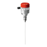
Visual representation of the DGS unit's dimensions and external appearance.

Cable Gland Opening Procedure

Status LED and Buzzer;Light Indicators

Explains the meaning of LED and Buzzer/Light indicators for status and errors.

Ackn.-;Test Button and DI_01 Functions

Details the function of the Ackn.-/Test button and DI_01 for testing and acknowledgment.

External Strobe & Horn Power Supply

Information on using the 24Vdc supply for external strobe and horn connections.

Jumper Configuration Settings

Explanation of how jumpers JP4 and JP5 affect communication and output settings.

DGS Installation and Configuration

Mounting and Wiring

Instructions for physically mounting the DGS unit and its wiring connections.

System Integration Details

Guidelines for integrating the DGS with Danfoss system managers or general BMS.

Sensor Replacement Guide

Procedure and information for replacing a DGS sensor unit.

DGS Installation Testing Methods

Optical Installation Check

Visual inspection of cable type and mounting height for correct installation.

Functional Test Procedure

How to perform a functional test by pressing the test button and checking outputs.

Zero-Point Test Procedure

Performing a zero-point test using fresh outdoor air for calibration.

Reference Gas Trip Test

Procedure for testing alarm functions using reference gas.

Sensor Specification Comparison

How the DGS software verifies sensor compatibility with its own specification.

Menu Survey Parameters

DGS Troubleshooting

Overview

The Danfoss Gas Sensor (DGS) is a safety device designed to detect high gas concentrations and trigger alarm functions. It is crucial to understand that while the DGS provides alarm functions for leakages, it does not resolve or address the root cause of the leakage itself.

Function Description

The DGS operates by continuously monitoring gas levels and activating alarms when detected concentrations exceed predefined thresholds. It is available in configurations with one or two sensors, and can optionally include a Buzzer and Light (B&L) for audible and visual alarms. The device supports various gas types, including HFC groups 1, 2, and 3, CO2, and Propane.

The DGS is a digital device with self-monitoring capabilities, displaying internal errors via an LED and Modbus alarm messages. It integrates with Danfoss system managers or general BMS systems via Modbus communication. The device features an analog output (0-20mA or 0-10V) and relay outputs for critical and warning alarms.

Important Technical Specifications

  • Power Supply: 24Vdc or 24Vac.
  • Analog Output: Configurable as 0-20mA (JP5 open) or 0-10V (JP5 closed).
  • Modbus Baud Rate: Configurable as 19200 Baud (JP4 open) or 38400 Baud (JP4 closed, default).
  • Relay Outputs:
    • Warning Relay 1: SPDT NO (Normally Open)
    • Critical Relay 3: SPDT NC (Normally closed)
  • Sensor Types: Supports HFC gr.1 (R1234ze, R454c, R1234yf, R454a, R452A, R454b, R513a), HFC gr.2 (R407F, R416a, R417a, R407A, R422a, R427a, R449A, R437a, R134A, R438a, R422D), HFC gr.3 (R448A, R125, R404A, R32, R507A, R434a, R410A, R452b, R407C, R143b), CO2, and Propane (R290).
  • Full Scale Range: Varies by gas type (e.g., HFC: 2000 ppm, CO2: 20000 ppm, R290: 5000 ppm).
  • Alarm Thresholds: Configurable for warning and critical limits, both in % of range and ppm. Hysteresis of approximately 5% applies to alarm thresholds.
  • Alarm Delay: Configurable in seconds (0-600s).
  • Reset Alarm Time: Configurable in seconds (0-9999s), with 0 disabling the ability to reset.
  • Dimensions: 130mm (length) x 72mm (width) x 57mm (depth) for the main unit, with sensor heads extending further.

Usage Features

  • Installation: The unit must be installed by a suitably qualified technician according to instructions and industry standards. The sensor head should always be mounted pointing downwards. For gases heavier than air (HFC grp 1, 2, 3, CO2, Propane), the sensor head should be located approximately 30cm (12") above the floor, ideally in the air flow. Protective caps on catalytic bead sensors must be removed only after silicones are dry and the device is energized.
  • Cable Gland Opening: The enclosure allows for precision punching to create cable entry points.
  • Status LED / B&L:
    • GREEN: Power on (flashing if maintenance is needed).
    • YELLOW: Indicates an error (disconnected sensor, wrong sensor type, AO not configured/connected, sensor in special mode, supply voltage out of range, damaged sensor).
    • RED: Indicates an alarm due to gas concentration.
    • The Buzzer & Light behave identically to the status LED.
  • Ackn.-/Test Button / DI_01:
    • TEST: Pressing for 8 seconds simulates critical and warning alarms, driving AO to max (10V/20mA). Stops on release.
    • ACKN. (Acknowledge): If pressed during a critical alarm, relays and buzzer go out of alarm condition and reactivate after 5 minutes if the alarm persists. This function's duration and relay status inclusion are user-defined.
    • DI_01: A dry-contact input (terminals 1 and 2) that behaves identically to the Ackn./Test button.
  • Sensor Replacement: Sensors are connected via a plug connection, allowing for simple exchange without on-site calibration. The internal X-change routine automatically recognizes the new sensor, checks its type and measuring range against the existing configuration, and restarts measurement. If data mismatches, the status LED indicates an error.
  • Configuration: The DGS is pre-configured with factory-set defaults. Jumpers (JP4, JP5) are used to change the analog output type and Modbus baud rate.
  • System Integration: Modbus address can be set using the DGS Service Tool (password "1234").

Maintenance Features

  • Regular Test: To maintain performance and comply with local requirements, the DGS must be tested regularly. This includes activating the test button to validate alarm reactions and testing sensors via bump test or calibration.
  • Calibration Intervals:
    • DGS-IR: 60 months (annual bump test recommended in years without calibration).
    • DGS-SC: 12 months.
    • DGS-PE: 6 months.
    • Local regulations on calibration or testing should be checked.
    • After a substantial gas leak, the sensor should be checked by bump test or calibration and replaced if necessary.
  • Functional Test: For initial operation and maintenance, press the test button for more than 8 seconds and observe that all connected outputs (Buzzer, LED, Relay connected devices) are working correctly. Outputs should automatically return to their initial position upon deactivation.
  • Zero-point Test: If prescribed by local regulations, a zero-point test with fresh outdoor air can be performed. A potential zero offset can be read using the Service Tool.
  • Trip Test with Reference Gas: If prescribed by local regulations, the sensor can be gassed with reference gas (using a gas bottle with pressure regulator and calibration adapter) to exceed alarm thresholds and activate all output functions. This allows checking if connected output functions (e.g., horn, fan) are working correctly. Outputs should automatically return to their initial position after removing the reference gas.
  • Sensor Specification Comparison: The DGS software automatically reads and compares the specification of the connected sensor with the DGS specification, enhancing user and operating security. New sensors are factory-calibrated by Danfoss and do not require re-calibration during commissioning if still in original packaging and within the calibration certificate's validity.
  • Troubleshooting (LED Indicators):
    • LED off: Check power supply, wiring, and DGS Modbus for damage.
    • Green flashing: Calibration interval exceeded or sensor end-of-life. Requires calibration or sensor replacement.
    • Yellow: AO not connected, wrong sensor type/range, disconnected sensor, damaged sensor, or supply voltage out of range.
    • Yellow flashing: DGS in service mode from the handheld service tool.
    • Alarms in absence of leak: Try setting an alarm delay or perform a bump test.
    • Zero-measurement drifts: DGS-SC sensor technology is sensitive to environmental factors (temperature, moisture, cleaning agents, gases from trucks). Measurements below 75ppm should be disregarded; no zero-adjustment made.

Danfoss DGS Specifications

General IconGeneral
BrandDanfoss
ModelDGS
CategoryAccessories
LanguageEnglish

Related product manuals