© Danfoss | DCS (ADAP-KOOL®) | 2018.12
RI8SP202 | 2
Danfoss Gas Sensor DGS
Status LED / B&L:
GREEN is power on.
- flashing if maintenance needed
YELLOW is an indicator of Error.
- the sensor head is disconnected or not the
expected type
- AO configured as 0-20mA but no current is running
- flashing when sensor is in special mode (e.g. when
changing parameters with the service tool)
- Supply voltage out of range
RED is an indication of alarm due to gas
concentration level.
The Buzzer & Light behaves identical to the status
LED.
Ackn. -/Test button / DI_01:
TEST - The button must be pressed for 8 sec.
- Critical and warning alarm is simulated and AO
goes to max. (10V/20mA), stop on release.
ACKN. - if pressed during critical alarm, as default*
the relays and buzzer goes out of alarm condition
and goes back on after 5 minutes if the alarm
situation is still active.
* the duration and whether to include the relay
status with this function or not is user defined
DI_01 (terminals 1 and 2) is a dry-contact (potential-
free) behaving identically to the Ackn./Test button.
DC-supply for external Strobe&Horn
Whether the DGS is powered by 24Vdc or 24Vac,
a 24Vdc power supply (max. 50mA) is available
between terminals 1 and 5 on connector x1
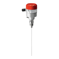
Jumpers
* JP4 open → 19200 Baud
JP4 closed → 38400 Baud (default)
* JP5 open → AO 0-20 mA
JP5 closed → AO 0-10 Volt (default)
Note: the DGS must be power cycled before any change to
JP4 take effect.
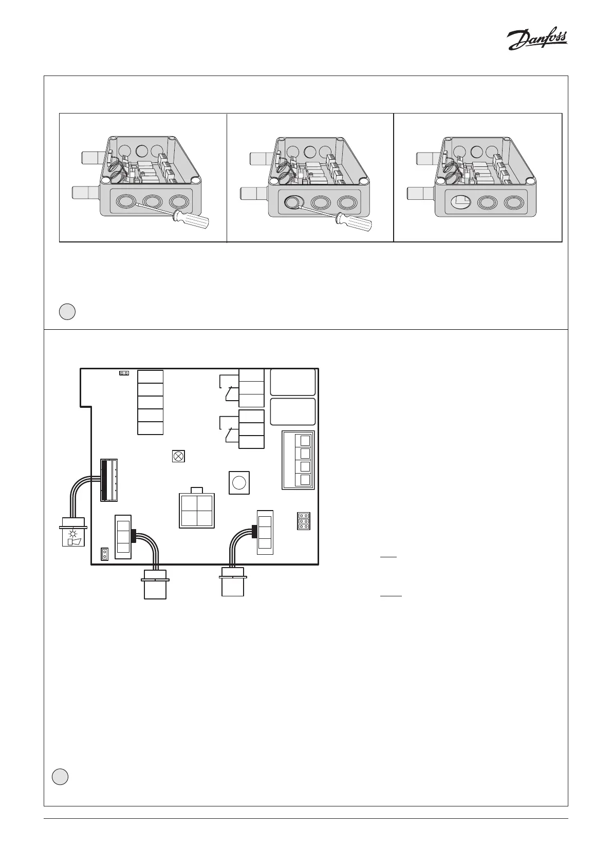
Cable Gland opening
148H126_01-2018
Hole punching for Cable gland:
1. Select the location for the safest cable entry.
2. Use a sharp screwdriver and a small hammer.
3. Place the screwdriver and hammer with precision
while moving the screwdriver within a small area
until the plastic is penetrated.
Continue precision punching with small movements
until the round piece can be pulled out by your
fingers.
Remove potential burrs and secure flat surfaces.
Install the Cable gland according to the enclosed guide.
2
3
JP5
5
4
2
1
not used
GND
AO_01
DI_01
S&H supply
x1
open: 0-20mA
closed: 0-10V
LED
Yellow/Green/Red
1
2
3
1
2
3
x6
x5
Rel. 3
Rel. 1
x4
4
3
2
1
not used
JP3
JP2
JP1
x3
Ackn.-/Test
button
Sensor 1
Sensor 2
Tool
x9
x2
x8
B&L
JP4
Danfoss
80Z790.1
open: 19200 Baud
closed: 38400 Baud
B-
Modbus
A+
-
+
(critical)
(warning)