17
180R9267 / IOM APP 1.5-3.5 Appendices - v04 / 11.2013
Instruction APP pump instruction APP 0.6-1.0, APP 1.5-2.5 and APP 3.0-3.5
4
180R9065 / 521B0733 / DKCFN.PI.013.C4.2T / 09.2012
2.4 General guidelines for calculation of
pressure losses
In order to avoid the risk of cavitation, the inlet
pressure at the pump must be in accordance
with the specifications mentioned in Data
sheet (521B0850).
The inlet line connection must be properly
tightened, as possible entrance of air will cause
cavitation.
The suction conditions can be optimized
according to below guidelines.
2.5 General comments on
Filtration
A good filtration is vital to ensure a long and
trouble free life of the pump.
When selecting a lter or strainer, please note
that lter materials should be compatible with
water, i.e. should neither corrode or dissolve. Also
be aware of the electrochemical series of the
applied materials.
Main lter must have a neness of 10 μm abs.
ß 10 >5000. The pressure loss across the lter
should be monitored.
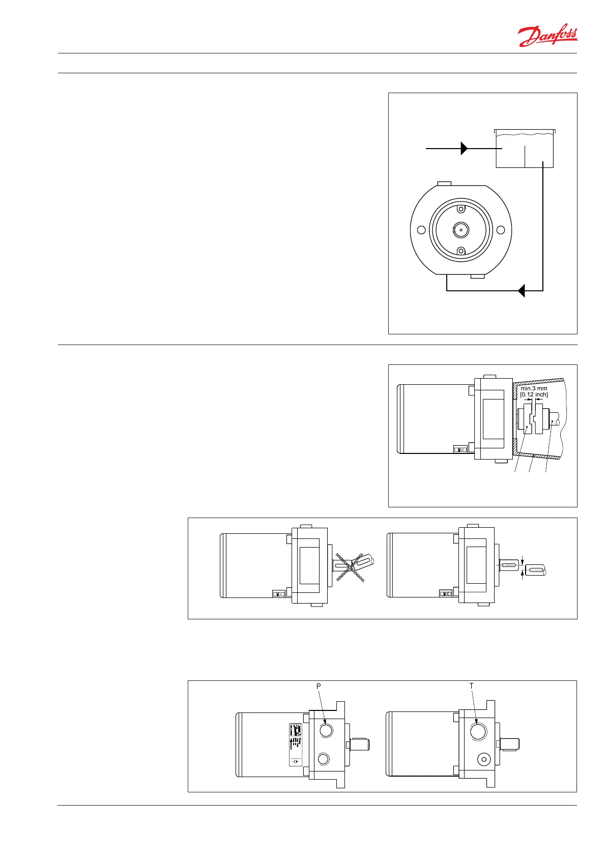
Water tank
Must be made of corrosion-proof material such
as stainless steel or plastic and must be sealed to
prevent entrance of impurities from the environ-
ment.
In smooth pipes and hoses
In 90° bends
In smooth pipes and hoses
Instruction APP pump instruction APP 0.6-1.0, APP 1.5-2.5 and APP 3.0-3.5
5
180R9065 / 521B0733 / DKCFN.PI.013.C4.2T / 09.2012
3. Building up the pump
unit
Automatic pressure equalization between tank
and surroundings must be ensured.
Inlet from the water supply and inlet to the
pump should be placed in opposite ends of the
tank to calm and deaerate the water, and to
ensure optimum opportunity for particles to
settle.
Pump suction line should be placed relatively
high above the tank bottom in order to prevent
settled particles from being led into the pump.
We recommend a separation (“wall”) to separate
the inlet from the outlet end of the tank.
Monitoring
It is recommended to continuously monitor the
following conditions:
• Water level in the tank
• Filter contamination
• Pressure (inlet- and outlet side of the
pump)
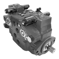
3.1 Mounting
(Please also see hints in “Right and Wrong”)
If alternative mounting is desired, please contact
the Danfoss Sales Organization.
Choose proper tolerances to ensure an easy
mounting of the elastic coupling without use of
tools.
Please take care to observe the recommended
length tolerances of the chosen coupling, as an
axial force on the pump will damage the pump.
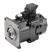
3.2 Direction of rotation
Is indicated by means of an arrow at the inlet side
of the pump.
P Outlet
T Inlet
max. 0.25 mm
max. 0.01 inch
A Elastic coupling
B Ball housing
C Motor shaft
A B C