Do you have a question about the Danfoss H1P Series and is the answer not in the manual?
General overview of hydrostatic system servicing procedures and manual scope.
Key procedures for maintaining pump cleanliness and integrity during service.
Essential safety guidelines for servicing hydraulic systems to prevent injury.
Explanation of symbols used throughout the manual for clarity and understanding.
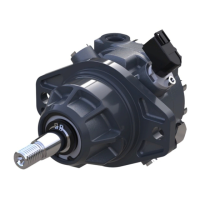
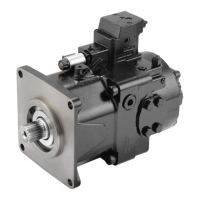
Overview of the H1 family's design, application, and capabilities.
Diagrams illustrating the basic closed circuit and case drain flow paths.
Visual representation of H1 single pumps and system schematics.
How pressure limiter valves regulate system pressure by adjusting swash plate position.
Internal view of the pressure limiter valve mechanism.
Function of HPRV for pressure limiting and charge check valve for oil replenishment.
Internal view of the HPRV/charge check valve assembly.
Function and settings of the charge pressure relief valve.
Method to bypass the HPRV valve for machine movement without charge pressure.
Schematic showing the function of an H1P pump with EDC control.
How EDC controls pump displacement via electrical signals.
Detailed operation of the EDC system, including feedback mechanisms.
Functionality of manual override for control actuation and diagnostics.
Operation of manual controls for pump displacement adjustment.
How the MDC controls pump displacement and its operational limitations.
Torque specifications for the MDC handle and input.
Functionality and data for the neutral start switch.
Usage of the M14 port for flushing residual contamination.
Recommended minimum, rated, and maximum operating speeds for the pump.
Factors affecting system pressure and its impact on hydraulic unit life.
Pressure in the servo system needed to position and hold the pump on stroke.
Function and settings of the charge pressure system for lubrication and control.
Inlet pressure requirements for the charge pump to avoid cavitation.
Limits and effects of case pressure on pump components and seals.
Pressure limits for the external shaft seal to prevent damage.
Recommended operating temperature ranges for hydraulic fluid.
Fluid viscosity recommendations for optimal performance and bearing life.
General design and connection specifications for H1 pumps.
Physical dimensions and properties for specific H1P pump models.
Recommended fluid types, viscosity, and temperature limits for operation.
Guidelines for selecting and maintaining hydraulic fluid filtration for cleanliness.
Identification of pump ports for pressure testing and gauge installation.
Detailed information on H1P pump port identification and sizes.
Table of port sizes, wrench sizes, and gauge specifications.
Safety warning regarding machine movement during startup procedures.
Step-by-step guide for safely starting up the pump after installation or maintenance.
Diagnosing and resolving issues related to high inlet vacuum and cavitation.
Safety warning concerning machine movement during troubleshooting.
Precautions for dealing with pressurized hydraulic fluid to prevent injury.
Guidelines for handling and disposing of hydraulic fluid safely and legally.
Steps for diagnosing electrical issues with pump controls and components.
Troubleshooting filter bypass indicator switch issues and filter status.
Steps to resolve issues with achieving neutral pump position.
Diagnosing and rectifying problems with unidirectional operation.
Identifying causes and solutions for system overheating issues.
Troubleshooting steps for a completely non-operational system.
Identifying and resolving sources of system noise and vibration.
Diagnosing and rectifying slow or sluggish system responses.
General steps for inspecting and preparing components for adjustment.
Procedure for checking and adjusting the charge pressure relief valve.
Steps for adjusting the pressure limiter settings according to model code.
How pump rotation direction affects pressure limiter settings.
Procedure for engaging the bypass function of HPRVs for machine movement.
Adjusting forward and reverse displacement limits on single pumps.
Procedure for setting the neutral position of the EDC control.
Method for setting mechanical neutral on EDC and non-feedback controls.
Identification of system pressure gauge ports used for neutral adjustment.
Steps for adjusting the servo cylinders to achieve neutral pump position.
General guidelines for pump removal and preparation for repair.
Procedures for repairing EDC control modules and components.
Steps for installing EDC control modules, ensuring proper alignment.
Repair procedures for pump control solenoids, including O-ring replacement.
Repair steps for the Manual Displacement Control (MDC) unit.
Repair and replacement of the angle sensor on EDC controls.
Procedures for repairing EDC units equipped with an angle sensor.
Notes and precautions for repairing automotive control systems.
Installation procedures for AC control modules and associated components.
Procedures for servicing the pump shaft, seals, and bearings.
Steps for installing the shaft and bearing assembly into the pump.
Procedure for servicing the external hydraulic filter assembly.
Repairing the filter bypass valve and associated switch.
Repair procedures for charge pumps with removable auxiliary pads.
Repair procedures for charge pumps with integrated auxiliary pads.
Steps for reassembling the charge pump components after repair.
Procedure for replacing High Pressure Relief Valve (HPRV) units.
Procedure for replacing the Charge Pressure Relief Valve (CPRV).
Steps for replacing Pressure Limiter (PL) valves.
Procedure for replacing the Pressure Limiter valve.
Identification of common fasteners and plugs used in the pump assembly.
Table detailing fastener sizes and their corresponding torque values.
Table specifying plug sizes and their corresponding torque values.
| Brand | Danfoss |
|---|---|
| Model | H1P Series |
| Category | Water Pump |
| Language | English |