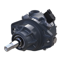
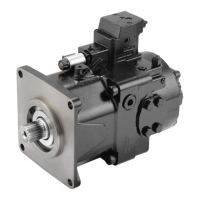
H1 Pumps General Specification
Axial piston closed circuit variable displacement pumps of cradle swash-plate design with clockwise or
counterclockwise direction of rotation.
Pipe connections
•
Main pressure ports: ISO split flange boss
•
Remaining ports: SAE straight thread O-ring boss
Recommended installation position
Pump installation position is discretionary, however the recommended control position is on the top or
at the side with the top position preferred. If the pump is installed with the control at the bottom,
flushing flow must be provided through port M14 located on the EDC, FNR and NFPE control.
Vertical input shaft installation is acceptable. If input shaft is at the top, 1 bar case pressure must be
maintained during operation. The housing must always be filled with hydraulic fluid. Recommended
mounting for a multiple pump stack is to arrange the highest power flow towards the input source.
Consult Danfoss for nonconformance to these guidelines.
Auxiliary cavity pressure
Auxiliary cavity pressure will be inlet pressure with internal charge pump or case pressure with external
charge supply. For reference see Operating Parameters. Please verify mating pump shaft seal capability.
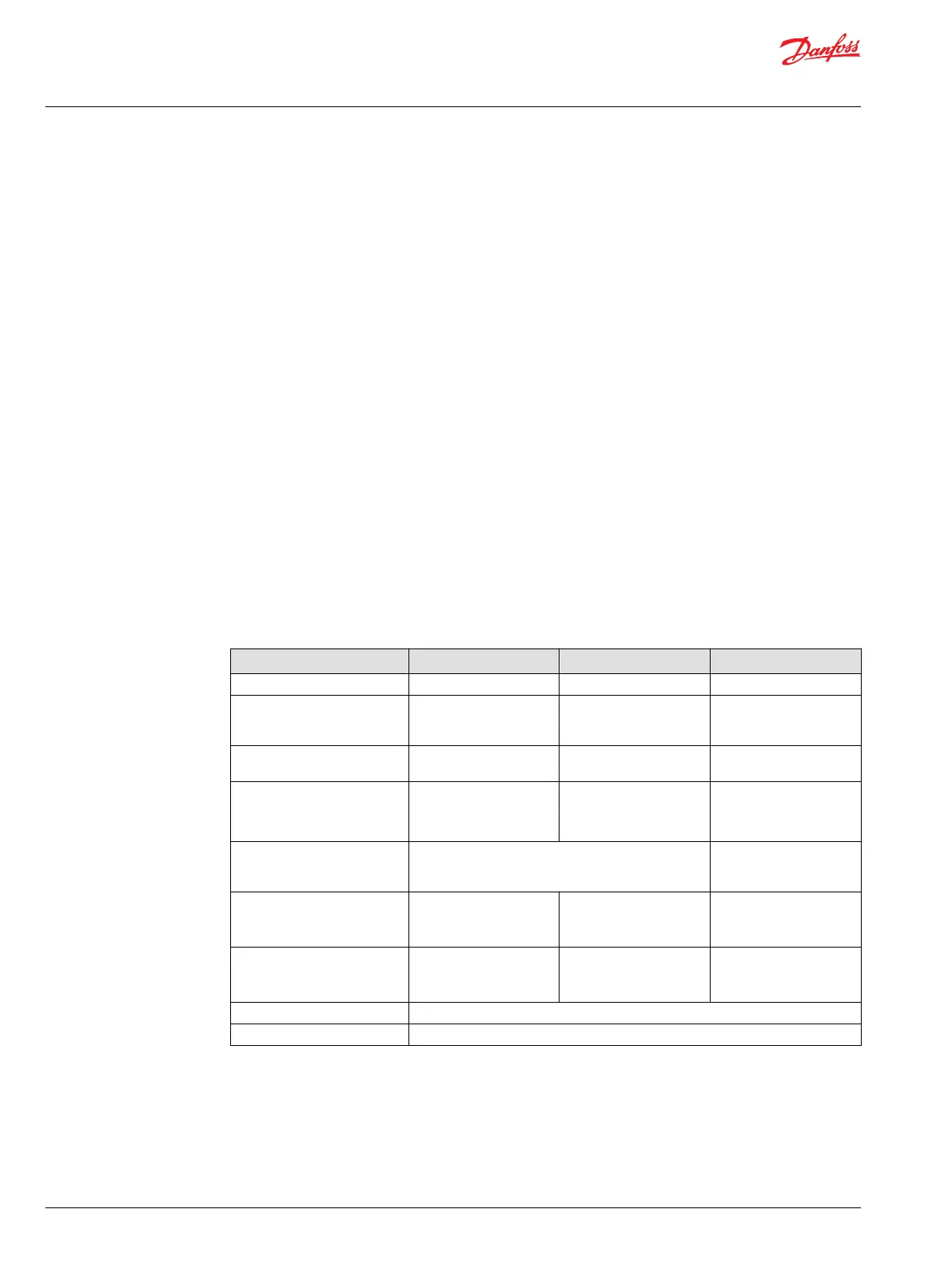
H1P 069—250 Physical Properties
Frame size 069/078, 089/100 115/130, 147/165 210/250
Oil volume 2.0 l [0.5 US gal] 3.0 l [ 0.8 US gal] 7.2 l [ 1.9 US gal]
Mounting flange SAE flange, size C (SAE J
744) mounting pad
SAE flange, size D (SAE J
744) mounting pad
SAE flange, size E (ISO
3019-1 flange 177-4)
mounting pad
Auxiliary mounting SAE A, SAE B, SAE B-B, SAE
C
SAE A, SAE B, SAE B-B, SAE
C, SAE D
SAE A, SAE B, SAE B-B, SAE
C, SAE D, SAE E
Splined Shafts
•
14-teeth 12/24
•
21-teeth 16/32
•
23-teeth 16/32
•
13-teeth 8/16
•
27-teeth 16/32
•
13-teeth 8/16
•
17-teeth 8/16
•
27-teeth 16/32
Suction port 1.625 [1 5/8] –12UN-2B Ø38 - 350 bar split flange
boss per ISO 6162
M12x1.75
Main port configuration Ø25.4 - 450 bar split
flange boss per ISO 6162
M12x1.75
Ø31.5 - 450 bar split
flange boss ISO 6162
M12x1.75
Ø38 - 450 bar split flange
boss ISO 6162
M16x2
Case drain ports L1, L3, L2, L4
(SAE O-ring boss).
0.875 [7/8] -12UNF-2B
1.0625 [1 1/16] -12UNF-2B
1.0625 [1 1/16] -12UNF-2B
1.3175 [1 5/16]-12UNF-2B
Port ISO 11926-1; 1
5/16-12 (SAE O-ring boss)
only L2 and L4
Other ports SAE O-ring boss
Customer interface threads Metric fastener
For more info see Port Locations and Gauge Installation on page 26
Service Manual
H1P 069—H1P 250 Axial Piston Single Pumps
Technical Specifications
22 |
©
Danfoss | September 2020 AX152886482551en-000504

 Loading...