M
Matthew JohnsonAug 19, 2025
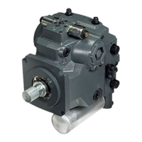
How to address a contaminated control orifice in a Danfoss H1T 045?
- RrobinsonjerryAug 19, 2025
If you suspect contaminated control orifices in your Danfoss Water Pump, it means the control orifices are plugged. Clean the control orifices.