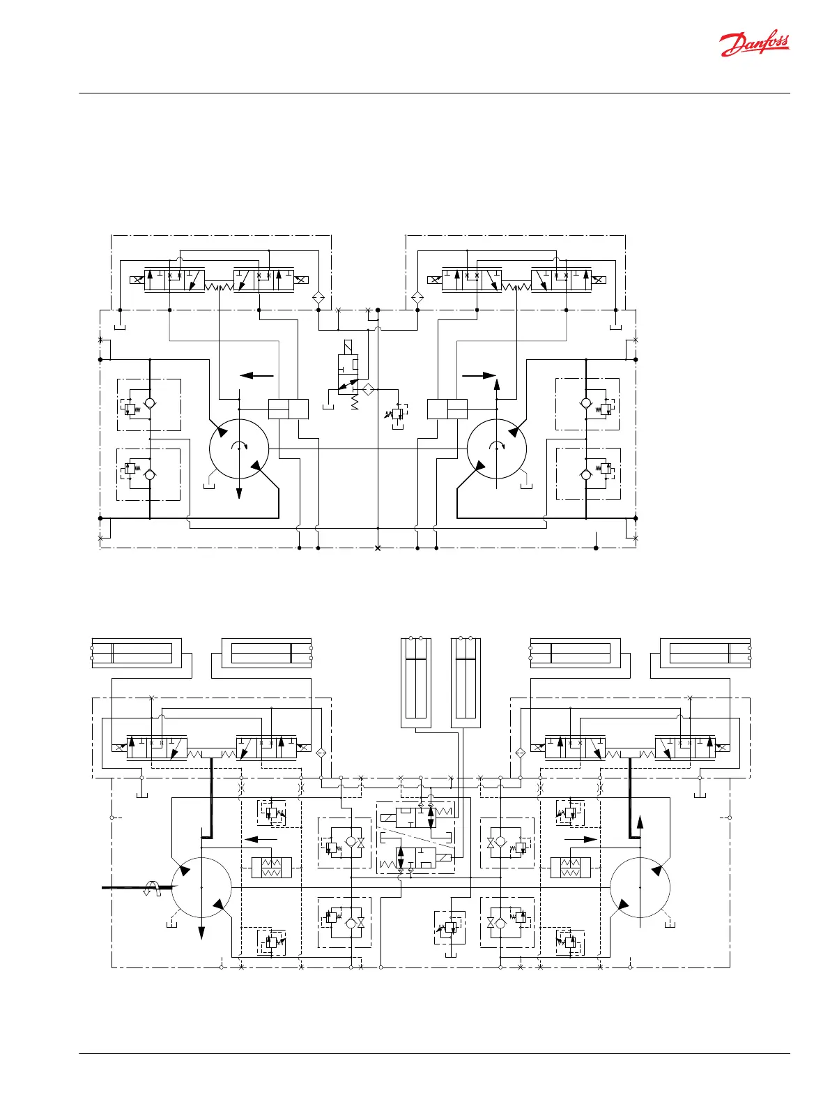
H1T Tandem Pumps Schematics
The schematics below show the function of an H1 tandem axial piston variable displacement pump with
electric displacement control (EDC) and optional control cut-off valve.
045/053 Tandem
P106 148E
M4
M5
M5
M4
M3
L3
MBMC
MA
MD
C
D
B
A
E
X7
C1
C2
C1
C2
CW
CW
Flow
out C
Flow
out A
060/068 Tandem
M5
M4
A
MA
MD
D
B MB
MC
C
M5
M4
H1 Tandem
E
M3
ccw
flow out B flow out D
C1 C2
M14
C1C2
M14
1
2
Supply/Ground
CONTROL SOLENOID C1
Ground/Supply
1
2
Supply/Ground
Ground/Supply
CONTROL SOLENOID C2
1
2
Supply/Ground
CONTROL SOLENOID C2
Ground/Supply
1
2
Supply/Ground
Ground/Supply
CONTROL SOLENOID C1
X7
1
2
Supply/Ground
Ground/Supply
CCO SOLENOID
1
2
Supply/Ground
Ground/Supply
BRAKE SOLENOID
L1
L3
P109541
Service Manual
H1T 045/053, 060/068 Axial Piston Tandem Pumps
Introduction
©
Danfoss | September 2020 AX152886481761en-000405 | 11