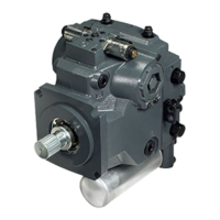
H1 Pumps General Specification
Axial piston closed circuit variable displacement pumps of cradle swash-plate design with clockwise or
counterclockwise direction of rotation.
Pipe connections
•
Main pressure ports: ISO split flange boss
•
Main pressure ports H1P 045/053: SAE straight thread O-ring boss
•
Main pressure ports H1P 060/068: ISO split flange boss
•
Remaining ports: SAE straight thread O-ring boss
Recommended installation position
Pump installation position is discretionary, however the recommended control position is on the top or
at the side with the top position preferred. If the pump is installed with the control at the bottom,
flushing flow must be provided through port M14 located on the EDC, FNR and NFPE control.
Vertical input shaft installation is acceptable. If input shaft is at the top, 1 bar case pressure must be
maintained during operation. The housing must always be filled with hydraulic fluid. Recommended
mounting for a multiple pump stack is to arrange the highest power flow towards the input source.
Consult Danfoss for nonconformance to these guidelines.
Auxiliary cavity pressure
Auxiliary cavity pressure will be inlet pressure with internal charge pump or case pressure with external
charge supply. For reference see Operating Parameters. Please verify mating pump shaft seal capability.
Technical Data for H1 Tandem Pumps
Technical Data
Feature Unit 045 053 060 068
Displacement cm
3
[in
3
] 45.0 [2.75] 53.8 [3.28] 60.4 [3.69] 68.0 [4.15]
Flow at rated (continuous) speed
*
l/min
[US gal/min]
153 [40] 183 [48] 210 [55.5] 238 [62.8]
Torque at maximum displacement
(theoretical)
N•m/bar
[lb•in/1000 psi]
0.8 [488] 0.9
[549]0.007
8 [0.00575]
0.96 [590] 1.08 [610]
Mass moment of inertia of rotating
components
kg•m
2
[slug•ft
2
]
0.0077
[0.00568]
0.0078
[0.00575
0.0143
[0.01055]
0.0143
[0.01052]
Mass (weight dry, without charge
pump or auxiliary flange)
kg [lb] 65 [143] 65 [143] 96.2 [212] 96.2 [212]
Oil volume l [US gal] 2.3 [0.61] 2.3 [0.61] 4.2 [1.1] 4.2 [1.1]
*
Applies for each rotating group.
Physical properties
Description 045/053 060/068
Mounting flange per ISO 3019-1 Flange 101-2 (SAE B), special bolt Flange 127-4 (SAE C)
Input shaft outer diameter, splines
per ISO 3019-1
•
Ø25 mm - 4 (SAE B-B, 15 teeth)
•
Ø32 mm - 4 (SAE-C, 14 teeth)
•
Ø31 mm - 4 (19 teeth)
•
Ø32 mm - 4 (SAE C, 14 teeth)
•
Ø35 mm - 4 (SAE C, 21 teeth)
Service Manual
H1T 045/053, 060/068 Axial Piston Tandem Pumps
Technical Specifications
©
Danfoss | September 2020 AX152886481761en-000405 | 27