Do you have a question about the Danfoss Series 90 and is the answer not in the manual?
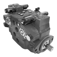
Overview of Series 90 hydrostatic pumps and motors for closed circuit applications.
Details on PLUS+1 compliant controls and sensors for compatibility with machine control architecture.
Provides general specifications for Series 90 axial piston pumps, including design and connections.
Lists key features and available options for Series 90 pumps, such as displacement and mounting.
Defines operating parameters and limitations for Series 90 pumps regarding speeds and pressures.
Specifies fluid properties and requirements, including viscosity, temperature range, and filtration.
Defines operating parameters and limitations for Series 90 pumps regarding speeds and pressures.
Details minimum, rated, and maximum input speed recommendations and limitations for pump operation.
Explains system pressure as a key variable affecting hydraulic unit life and defines working/maximum pressures.
Explains servo pressure in the servo-system needed to position and hold the pump on stroke.
Details charge pressure regulation, including settings, minimum, and maximum values.
Defines rated and maximum case pressure limits, with cautions on exceeding them.
Specifies maximum differential pressure limits for the input shaft seal to prevent damage.
Discusses temperature limits and fluid viscosity requirements for optimal pump performance and life.
Importance of clean fluid and recommended filtration levels (ISO 4406, Beta ratio) for preventing wear.
Discusses suction filtration (Option S) and pressure filtration strategies, including filter efficiency.
Details suction filtration, including the circuit layout and recommendations for contamination monitoring.
Explains charge pressure filtration types (remote/integral) and their benefits for fluid cleanliness.
Describes the availability of a special adapter head for convenient remote charge filter location and service.
Guidelines for selecting hydraulic fluids based on oxidation, rust, foam inhibitors, and stability properties.
Guidelines for hydrostatic system reservoir volume, fluid dwell, and outlet/inlet positioning for de-aeration.
Specifies requirements for case drain routing to maintain pump housing oil volume and manage case pressure.
Factors influencing pump life, including speed, pressure, and swashplate angle, with contact for detailed calculation.
Explains the function and requirements of the charge pump in Series 90 axial piston pumps.
Provides guidelines for charge pump sizing and selection, considering system features and conditions.
Discusses bearing life considerations for different drive types and factors affecting it.
Details considerations for external shaft loads (side/thrust) and their impact on bearing life.
Explains sources of noise (fluid-borne, structure-borne) and provides suggestions for minimization.
Provides equations for sizing hydraulic pumps, covering flow, torque, and power calculations in SI and US units.
Addresses potential excessive loading on the mounting flange from tandem pumps or shock loads.
Explains how to estimate overhung load moments based on pump mass, acceleration factors, and application type.
Presents a table of allowable rated and shock load moments for different frame sizes.
Explains the structure of the Series 90 master model code for defining pump configurations.
Continues the explanation of the Series 90 master model code structure for pump configurations.
Details options for high pressure regulation, including pressure limiters and relief valves.
Specifies available auxiliary mounting pad options (SAE A, B, C, etc.) and their spline couplings.
Describes options for limiting pump displacement, including settings for forward and reverse.
Lists available shaft options for Series 90 pumps, including splined and tapered shaft types.
Details the charging system options for Series 90 pumps, specifying charge pump sizes and flow rates.
Describes various control orifice options for MDC, EDC, FNR, HDC, and NFPE controls, specifying flow rates.
Details special hardware features available for Series 90 pumps, such as speed sensing and valve plate options.
Specifies high pressure settings (A) available for Series 90 pumps, defined in bar.
Lists the available charge pressure settings for Series 90 pumps, specified in bar.
Describes the 3-position (FNR) electric control using input signals to switch the pump to full stroke positions.
Provides electrical data for solenoids used in FNR controls, including voltage, current, and connector types.
Explains factors affecting response time for FNR controls and the availability of orifice sizes for tuning.
Explains EDC using a Pressure Control Pilot (PCP) valve to convert electrical input to hydraulic signals for servo pistons.
Lists features and benefits of the electric displacement control, such as high gain and neutral return.
Details electrical characteristics of EDC controls, including dual coil operation and current/voltage requirements.
Specifies control signal requirements for EDC, including PWM frequency and maximum input current.
Pin assignment for MS connector used with EDC control option KA.
Pin assignment for Packard Weather-Pack connector used with EDC option KP.
Pin assignment for Deutsch DT Series connector used with EDC option KT.
Table showing pump output flow direction based on input shaft rotation and control signal for EDC.
Introduces the Manual Over Ride (MOR) for temporary actuation of pump controls during diagnostic testing.
Explains HDC using hydraulic input signals to operate a servo valve and tilt the swashplate for displacement control.
Describes how the HDC control operates by porting hydraulic pressure to servo pistons to tilt the swashplate.
Lists features and benefits of HDC, including high gain control and low cost design.
Provides a hydraulic schematic illustrating the hydraulic displacement control system.
Explains factors affecting response time for HDC and the availability of orifice sizes for tuning.
Graph showing pump displacement relationship with hydraulic signal pressure for HDC.
Explains MDC using mechanical input signals converted to hydraulic signals to tilt the swashplate.
Provides a hydraulic schematic for the manual displacement control system.
Specifies torque requirements for moving and holding the control handle for MDC.
Graph showing pump displacement relative to control lever rotation for MDC.
Explains factors affecting response time for MDC and the availability of orifice sizes for tuning.
Table showing pump output flow direction based on input shaft rotation and handle rotation for MDC.
Explains the function of the Neutral Start Switch (NSS) in MDC to prevent prime mover start unless the pump is in neutral.
Describes NFPE as an electrical control using proportional solenoids that port charge pressure to servo cylinders.
Discusses control response for NFPE and the use of software for swashplate response control.
Details how NFPE control can be used with a Danfoss microcontroller for enhanced functionality.
Specifies input signal requirements for NFPE control, emphasizing PWM input current and frequency.
Provides detailed solenoid data for NFPE controls, including voltage, current, resistance, and PWM range.
Shows the relationship between NFPE pump displacement and input signal (shaft rotation, active solenoid).
Details multi-function valves that integrate pressure limiting systems and high pressure relief valves for overpressure protection.
Explains the sequenced pressure limiting system and high pressure relief valves for robust overpressure protection.
Describes how the pressure sensing valve and servo pressure relief valves limit system pressure and control displacement.
Explains the bypass function for moving vehicles without operating the prime mover, by rotating a bypass hex.
Lists and describes the available auxiliary mounting pad options (SAE A, B, C, D, E) for mounting other pumps.
Outlines mating pump requirements, including flange and shaft dimensions for auxiliary pump mounting.
Describes optional mechanical displacement limiters that set maximum displacement independently for forward and reverse.
Cautionary note regarding potential leakage when adjusting the displacement limiter while the machine is running.
Specifies the location of the displacement limiter on the servo side or high pressure side of the pump.
Explains the rated torque for splined shafts and the importance of lubrication for spline life.
Discusses spline engagement, radial loads, and shaft availability for determining operating life.
Presents data on shaft availability and maximum input torque for splined shafts across different frame sizes.
Provides information on shaft availability and maximum input torque for tapered shafts.
Acknowledgment required from the customer regarding analysis and design for tapered shaft couplings.
Explains the function and requirements of the charge pump in Series 90 axial piston pumps.
Provides guidelines for charge pump sizing and selection, considering system features and conditions.
Lists available charge pump sizes (cm³) and their corresponding rated speed limits (min⁻¹).
Describes the optional speed sensor for direct speed measurement, its mounting, and output signal.
Details the electrical specifications for the speed sensor, including supply voltage, current, and output voltage.
Specifies the operating and storage temperature range for the speed sensor.
Table showing pulse frequency per revolution for different frame sizes.
Provides pin assignment details for various connectors used with Series 90 pumps (Deutsch, Delphi, Turck).
Provides detailed installation drawings and dimensions for Frame Size 042 pumps.
Shows dimensions for the manual displacement control handle, including torque specifications.
Shows installation drawings for auxiliary mounting pads AB, BC, and BB, including coupling spline data.
Illustrates shaft dimensions for various options, including tapered shafts and spline details.
Provides detailed installation drawings and dimensions for Frame Size 055 pumps.
Shows dimensions for the manual displacement control handle for Frame Size 055.
Continues detailed installation drawings and dimensions for Frame Size 055 pumps.
Shows installation drawings for auxiliary mounting pads AB, BC, CD, and BB, including coupling spline data.
Continues installation drawings for auxiliary mounting pads AB, BC, CD, and BB.
Illustrates shaft dimensions for various spline and tapered shaft options.
Provides detailed installation drawings and dimensions for Frame Size 075 pumps.
Shows installation drawings for MDC with endcap side ports (Option 60) for Frame Size 075.
Shows dimensions for the manual displacement control handle for Frame Size 075.
Shows installation drawings for MDC with endcap twin ports (Option 80) for Frame Size 075.
Shows installation drawings for auxiliary mounting pads AB, BC, CD, and BB, including coupling spline data.
Shows installation drawings for auxiliary mounting pads AB, BC, CD, DE, EF, EG, BB.
Provides installation drawings for Frame Size 075 with NFPE options FK, FL, FM, FN.
Continues installation drawings for integrated NFPE control with endcap side ports.
Provides installation drawings for integrated NFPE control with endcap twin ports.
Illustrates shaft dimensions and coupling details for various options.
Continues illustration of shaft dimensions, spline types, and torque ratings.
Provides detailed installation drawings and dimensions for Frame Size 100 pumps.
Shows installation drawings for MDC with endcap side ports (Option 60) for Frame Size 100.
Shows dimensions for the manual displacement control handle for Frame Size 100.
Shows installation drawings for MDC with endcap twin ports (Option 80) for Frame Size 100.
Shows installation drawings for auxiliary mounting pads SAE A, B, C, including coupling spline data.
Shows installation drawings for auxiliary mounting pad SAE B-B, including coupling spline data.
Illustrates shaft dimensions and coupling details for various options.
Continues illustration of shaft dimensions, spline types, and torque ratings.
Provides detailed installation drawings and dimensions for Frame Size 130 pumps.
Shows installation drawings for MDC with endcap twin ports (Option 80) for Frame Size 130.
Shows dimensions for the manual displacement control handle for Frame Size 130.
Shows installation drawings for auxiliary mounting pads AB, BC, CD, DE, EF, EG, BB.
Continues installation drawings for auxiliary mounting pads AB, BC, CD, DE, EF, EG, BB.
Illustrates shaft dimensions and coupling details for various spline and tapered shaft options.
Provides detailed installation drawings and dimensions for Frame Size 180 pumps.
Shows installation drawings for MDC with endcap twin ports (Option 80) for Frame Size 180.
Shows dimensions for the manual displacement control handle for Frame Size 180.
Shows installation drawings for auxiliary mounting pads AB, BC, CD, DE, EF, EG, BB.
Continues installation drawings for auxiliary mounting pads AB, BC, CD, DE, EF, EG, BB.
Illustrates shaft dimensions and coupling details for various spline and tapered shaft options.
Provides detailed installation drawings and dimensions for Frame Size 250 pumps.
Shows installation drawings for MDC with endcap twin ports (Option 80) for Frame Size 250.
Shows dimensions for the manual displacement control handle for Frame Size 250.
Shows installation drawings for auxiliary mounting pads AB, BC, CD, DE, EF, EG, BB.
Continues installation drawings for auxiliary mounting pads AB, BC, CD, DE, EF, EG, BB.
Illustrates shaft dimensions and coupling details for various spline and tapered shaft options.
Provides dimensional data for cover plates and displacement limiter options across different frame sizes.
Shows installation drawings for the 3-Position (FNR) Electric Control for various frame sizes.
Provides installation drawings and dimensions for EDC with MS or Packard connectors.
Shows installation drawings and dimensions for Hydraulic Displacement Control (HDC).
Provides installation drawings and dimensions for MDC with a neutral start switch.
Shows installation drawings and dimensions for Electrohydraulic Displacement Control (NFPE).
Provides installation drawings for pumps with integral pressure filters (options P & L).
Shows installation drawings for pumps with remote pressure filtration (options R & T).
Summarizes filter dimensions (F1-F7 maximum) for various frame sizes and options.
| Brand | Danfoss |
|---|---|
| Model | Series 90 |
| Category | Water Pump |
| Language | English |