T
P
TM4 M5
P C P
X2
X1
P102 025
To use the EDC control in a PLUS+1 Guide application, download HWD file 10106626 from
www.Danfoss.com/Plus1.
Electrical Characteristics
7 mA with 0.25 Vdc
43 mA with 1.55 Vdc
Clockwise
Clockwise
Counterclockwise
Counterclockwise
Start Current
Full Stroke Current
Start Current
Full Stroke Current
T
F
A
H
S
P
M
U
P
N
O
I
T
A
T
O
R
L
A
C
I
R
T
C
E
L
E
S
T
N
E
M
E
R
I
U
Q
E
R
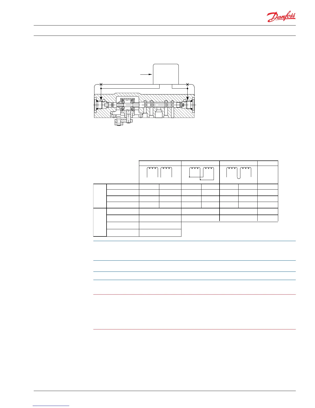
A or C
B or D
A and C A
D
One of Dual Coils
Dual Coils in Parallel
Dual Coils in Series
A
B
B
A
Produces
Flow Out of
Pump Port
A or C
A and C
A
B or D
B and D
D
B and D
14 mA with 0.13 Vdc
85 mA with 0.75 Vdc
A B C D
+ phasing to terminals
B C DA
+ phasing to terminals
B C DA
+ phasing to terminals
A/B 14 mA
± 3 mA
A/B 85 mA
± 11 mA
C/D 14 mA
± 3 mA
C/D 85 mA
± 11 mA
P108 497E
with 1.7 Vdc
with 0.3 Vdc
with 0.23 Vdc
with 1.36 Vdc
The EDC is designed to be controlled from a DC current source or voltage source. Pulse width modulation
(PWM) is not required. If a PWM signal is used to carry frequency greater than 200 Hz, do not use a pulse
current of more than 120% of that required for full output.
Control signal requirements
Recommended PWM signal is 200 Hz, avoid exceeding 440 Hz.
Warning
Maximum input current under any condition: 250 mA
PWM frequency: 200 Hz
Coil resistance at 24°C [75°F]:
A-B coil 20 Ω
C-D coil 16 Ω
Technical Information
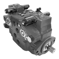
Series 90 Axial Piston Pumps
Control Options
520L0603 • Rev 0804 • March 2016 29