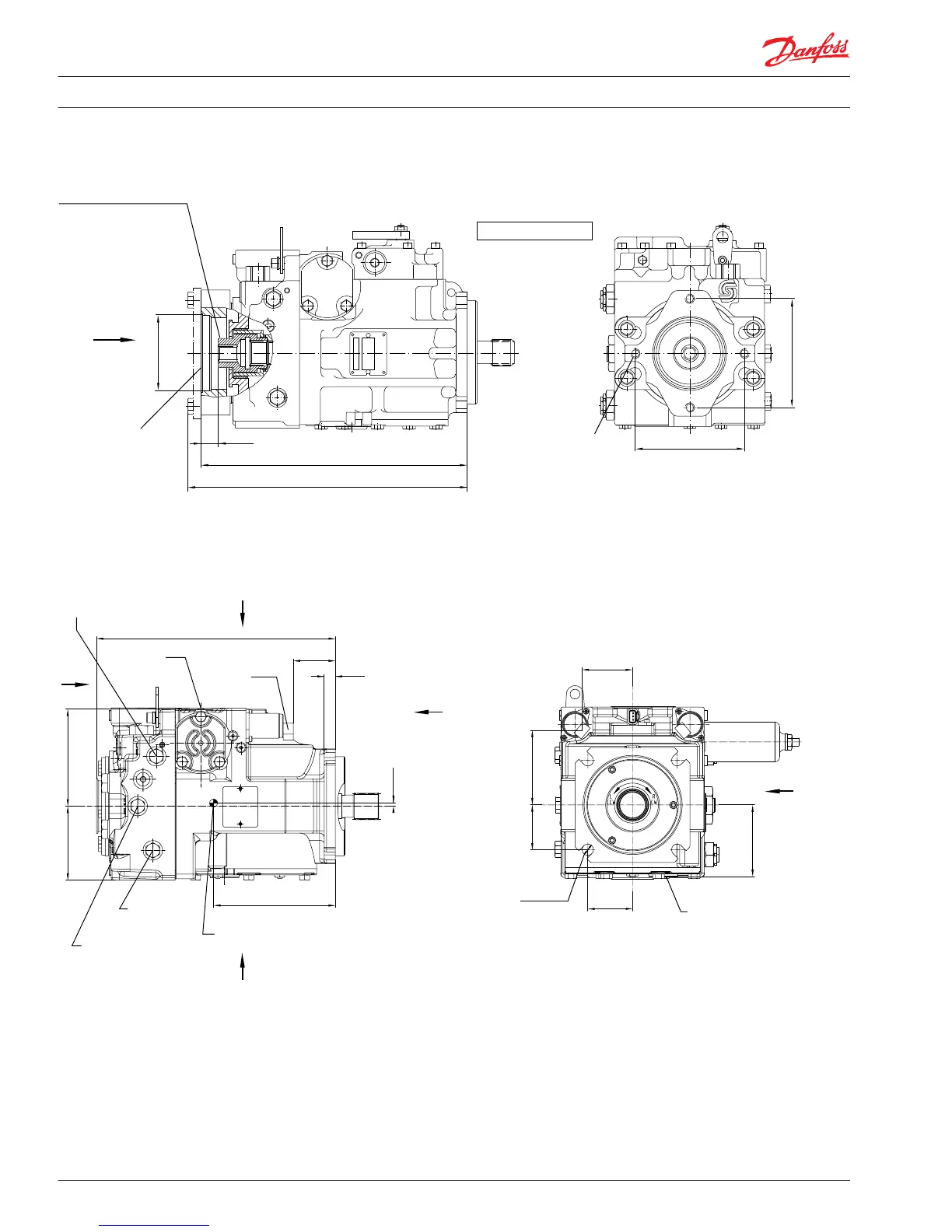
Auxiliary mounting pad – options AB, BC, CD, BB
A
M10
M3
M2M1
SAE B-B, option BB
View "X"
146
[5.75]
4 threads
1/2-13UNC-2B
22 [0.87] deep
146
[5.75]
346.5
[13.64]
328.9
[12.95]
For O-ring
Ø 94.92 x 2.62
[Ø 3.737 x 0.103]
"X"
Coupling spline data:
Pitch diameter = 23.8125 [0.9375]
Pressure angle = 30°
Number of teeth = 15
Pitch = 16/32
ANSI B92.1-1970, class 6,
fillet root side fit
Length of spline = 24.43 [0.96]
Ø 101. 65
[Ø 4.002]
+ 0.13
0
[+0.005]
[- 0.000]
22.75
[0.896]
2
B
M4M5
P102 049
Frame Size 075 NFPE Options FK, FL, FM, FN
Integrated NFPE control, endcap side ports
54
[2.118]
306
[12.043]
14
[0.56]
4
[0.157]
124.2
[4.89]
94.5
[3.722]
156
[6.142]
Connector
AMP Junior Typ A
Case drain L1
1-1/16-12UN-2B
System pressure B
Gage port M2
9/16-18UNF-2B
System pressure A
Gage port M1
9/16-18UNF-2B
Approx center
of gravity
Charge pump inlet M10
9/16-18UNF-2B
"E"
"B"
"A"
"C"
Ø14.3
[0.565]
57.25
[2.254]
95
[3.755]
65
[2.543]
91.7
[3.611]
+0.25
-0.13
[+0.10]
[-0.005]
57.25
[2.254]
Case drain L2
1-1/16-12UN-2B
"D"
View "B"
P104 324E
to case drain L1
Technical Information Series 90 Axial Piston Pumps
Installation Drawings
60 520L0603 • Rev 0804 • March 2016