Do not over torque the fitting on case drain port L2 (located on the side cover). The proper torque is 100
N•m [74 lbf•ft] maximum. Over torquing the fitting may change the neutral position of the swashplate.
Pump Life
Pump life depends on several factors, such as speed, pressure, and swashplate angle. For detailed
product life calculation, please contact your Danfoss representative.
Charge Pump
Charge flow is required on all Series 90 pumps applied in closed circuit installations. The charge pump
provides flow to make up internal leakage, maintain a positive pressure in the main circuit, provide flow
for cooling and filtration, replace any leakage losses from external valving or auxiliary systems, and to
provide flow and pressure for the control system.
Many factors influence the charge flow requirements and the resulting charge pump size selection. These
factors include system pressure, pump speed, pump swashplate angle, type of fluid, temperature, size of
heat exchanger, length and size of hydraulic lines, control response characteristics, auxiliary flow
requirements, hydrostatic motor type, etc. When initially sizing and selecting hydrostatic units for an
application, it is frequently not possible to have all the information necessary to accurately evaluate all
aspects of charge pump size selection.
Unusual application conditions may require a more detailed review of charge pump sizing. Charge
pressure must be maintained at a specified level under all operating conditions to prevent damage to the
transmission. Danfoss recommends testing under actual operating conditions to verify this.
Charge pump sizing/selection
In most applications a general guideline is that the charge pump displacement should be at least 10 % of
the total displacement of all components in the system. Unusual application conditions may require a
more detailed review of charge flow requirements. Refer to Selection of Drive line Components, BLN-9885,
for a detailed procedure.
System features and conditions which may invalidate the 10 % guideline include (but are not limited to):
•
Continuous operation at low input speeds (< 1500 min-1 (rpm))
•
High shock loading and/or long loop lines
•
High flushing flow requirements
•
Multiple Low Speed High Torque motors
•
High input shaft speeds
Bearing Loads and Life
In vehicle propel drives with no external shaft loads , and where the system pressure and swashplate
angle are changing direction and magnitude regularly, the normal L20 bearing life (80% survival) will
exceed the hydraulic life of the unit.
In non-propel drives, such as vibratory drives, conveyor drives and fan drives, the operating speed and
pressure are often nearly constant and the swashplate angle is predominantly at maximum. These drives
have a distinct duty cycle compared to a propulsion drive. In these types of applications, a bearing life
review is recommended.
For bearing life, speed, pressure, swashplate angle, plus external loads will be considered. Other factors
that affect bearing life include fluid type, viscosity, and cleanliness.
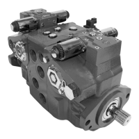
Technical Information
Series 90 Axial Piston Pumps
System Design Parameters
16 520L0603 • Rev 0804 • March 2016